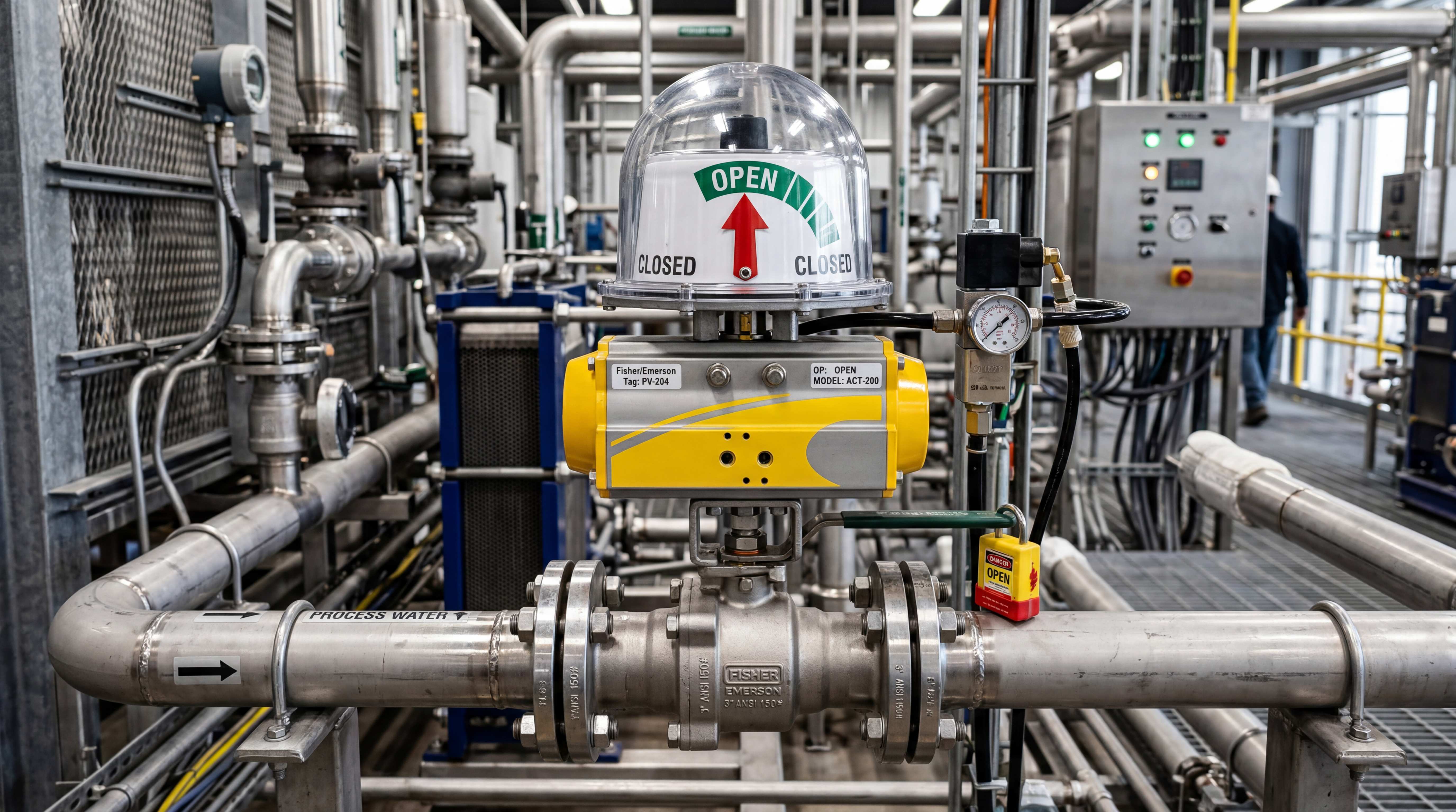
Automated Ball Valve FAT: Tests, Acceptance Criteria and Required Records
The Valve Moves. Is It Ready to Ship?
A supplier demonstrates an automated ball valve opening and closing. The local indicator turns, a green lamp comes on, and a short video reaches the buyer. That demonstration answers a useful question: something moved under the conditions shown. It does not, by itself, establish whether the purchased assembly meets its acceptance requirements. The lamp could represent an actuator switch rather than the valve's verified endpoint. The tested accessory could differ from the approved bill of materials. The movement could have occurred with a utility supply unavailable at the installation.
An automated ball valve FAT is an agreed factory acceptance test of an identified valve assembly against approved requirements. Its practical output is a traceable decision: which requirements passed, which failed, which remain untested, and what evidence permits shipment. Procurement teams need that decision before expediting a delivery. Quality teams need the supporting records. Engineers need to understand the limits of what the factory actually demonstrated.
This guide addresses assembled on-off ball valve packages after their configuration has been approved. It develops an original buyer-side acceptance framework, including a test matrix, a worked disposition example, and a release dossier. The proposed forms are editorial recommendations for project adaptation, not reproductions of a standard. Pressure limits, leakage criteria, test sequences, and safety arrangements must come from the applicable contractual documents and qualified test procedures.
The central discipline is straightforward: attach every acceptance statement to a requirement, a physical configuration, a test condition, and a result. A record containing all four can support a review months later. A checked box marked “operation satisfactory” often cannot explain what was tested, what changed afterward, or whether the delivered item is the one the witness observed.
Agree on the Decision Before Booking the Witness
Separate production testing from buyer acceptance
A valve factory acceptance test may include review of production records, additional witnessed tests, or both. The distinction should be settled before the inspection date. A manufacturer's normal production checks do not automatically satisfy every purchase-order requirement, while repeating a completed test without a defined purpose may add delay without improving the buyer's decision. Identify which results can be accepted through document review and which activities require an additional demonstration.
Valmet's explanation of its testing process distinguishes routine valve checks from FAT activities arranged around customer requirements. It is a useful manufacturer example of why the agreed scope matters, rather than evidence that every supplier follows the same inspection or witnessing percentage. See Valmet's overview of product testing and customer FAT.
Define the tested population separately from the witnessed population. A buyer may witness selected units while requiring specified production tests on every unit. Conversely, one demonstrated sample cannot substantiate a claim that all assemblies received the same functional verification unless individual records support that claim. Selection methods, expanded inspection after failures, and any permission to use representative samples belong in the approved plan. There is no universal sample percentage appropriate to every order.
Make the inspection plan a working agreement
The valve inspection and test plan should connect each activity with its responsible party, acceptance document, required record, and intervention point. Define what hold, witness, and review mean for the particular contract. State the notification period and what happens if a nominated witness cannot attend. A supplier should not have to guess whether an unanswered invitation permits the activity to proceed or whether written authorization is required.
IEC 62381:2024 provides a framework for acceptance and integration testing of process automation systems, including agreement on scope and responsibilities. Its public description supports project-specific planning; it does not establish universal pressure or leakage limits for ball valves. Use IEC 62381:2024 where applicable to the automation testing framework, alongside the actual valve product requirements and approved supplier procedures.
Resolve conflicting documents before the witness arrives. A data sheet may call for one failure position while the approved pneumatic drawing shows another. A purchase specification may require a measured closing time, while the proposed form provides only a pass box. Document the discrepancy, identify the authorized technical decision maker, and revise the controlling material. Quietly choosing the easier interpretation creates an acceptance dispute that the test itself cannot resolve.
An acceptance matrix that exposes missing evidence
The following actuated valve FAT checklist is organized by the question each test answers. Replace its acceptance-basis descriptions with precise project references before use. Add the equipment tag, serial number, procedure revision, responsible parties, and record identifiers to each applicable row. Mark a genuinely excluded activity with an approved reason; leaving a blank field makes an exclusion indistinguishable from an oversight.
| Decision area | Acceptance basis to identify | Evidence to retain | What this does not establish |
|---|---|---|---|
| Assembly identity | Approved data sheet, BOM, drawings and substitutions | Tag and serial cross-reference; configuration check | Functional performance |
| Pressure boundary | Applicable product standard and approved pressure-test procedure | Applicable shell-test record and conditions | Closed-seat leakage or actuator performance |
| Seat tightness | Specified leakage criterion, direction and test method | Result, units or observation method, conditions and duration | Leakage performance under every service condition |
| Normal operation | Approved control description and assembly procedure | Commands, actual movement, endpoints and anomalies | Operation under untested process loads |
| Travel timing | Defined start/stop events and project time window | Measured values for each required direction and condition | Site sequence timing with different interfaces |
| Failure response | Approved cause-and-effect requirements | Exact loss event, initial state, response and restoration behavior | Complete safety-function validation |
| Feedback | Wiring diagram, signal list and endpoint criteria | Physical reference, terminal states and agreed signal behavior | Seat sealing or untested plant-system mapping |
| Release | Contractual release conditions and authority | Completed dossier, dispositions and authorization | Permission to operate the installed plant |
At the Bench: Identify the Assembly and the Test Conditions
Keep the tested configuration connected to the shipped configuration

Start the acceptance record with the complete assembly identity, not just the purchase-order number. Connect the plant tag to the valve serial number, actuator identification, and relevant accessory models. Include the approved drawing and bill-of-materials revisions. An order containing many visually similar units needs an index that prevents a pressure certificate for one valve from being attached to another package.
Check differences that can change the result even when the valve and actuator nameplates match. Examples include the pilot valve function, regulator arrangement, speed-control setting, feedback device, control voltage, coupling orientation, and configured operating mode. Where settings are adjustable, record the approved as-tested values or export the relevant configuration. A component substitution after testing may require a review of the affected evidence, even if purchasing considers it commercially equivalent.
Use the existing guide to complete pneumatic valve package specification for the supply boundary and component responsibilities. At FAT, the question shifts from what should be supplied to whether the identified assembly matches that approved boundary. Record any temporary hoses, external controls, or substitute accessories used on the bench, and explain which conclusions those differences limit.
Assembly inspection also needs a clear endpoint. If an actuator is removed after testing to reduce shipping height, identify the reassembly controls and any verification that must follow. If electrical terminals are disconnected for packing, preserve terminal identification and the as-tested drawing. A shipment can remain physically undamaged while losing the configuration on which its acceptance was based.
Make measurements usable for the acceptance decision
Record the supply conditions at relevant points in the package, using the approved method. A workshop compressor setting is not necessarily the pressure available at the actuator during movement. Similarly, a nominal electrical supply label does not document the conditions experienced by an electric actuator. Identify the measurement location and whether the reading represents a static value, a dynamic observation, or a recorded range.
NIST explains that metrological traceability concerns a measurement result and its documented calibration chain, and that traceability alone does not guarantee fitness for purpose. In practical acceptance records, identify the instrument, method, range, resolution, calibration status, and relevant uncertainty. These details help establish whether a result can support the stated limit. See NIST's metrological traceability guidance, especially its discussion of suitability and calibration evidence.
Agree how borderline measurements will be evaluated before collecting them. If a measured travel time falls close to the contractual limit, an instrument display with too little resolution may not support a confident decision. The same issue arises when the leakage measurement method cannot distinguish the permitted result from an unacceptable one. Resolve the measurement capability or apply the agreed decision rule; do not round a marginal reading toward a pass.
Keep acceptance planning separate from the physical safety procedure. Pressure testing, electrical testing, and stored-energy operation require competent personnel, suitable facilities, and approved protective arrangements. This article defines evidence and review questions, not instructions for pressurizing or energizing equipment. The purchaser's attendance does not replace the test facility's responsibility for safe execution.
Read Pressure and Leakage Evidence on Its Own Terms

Ball valve shell and seat testing addresses different acceptance questions. A shell test concerns the pressure boundary under the specified test conditions. A seat test concerns leakage through the closed valve under a defined method and acceptance criterion. Combining both into a single statement such as “pressure tested, passed” can conceal which activity was performed and whether its conditions match the order.
ISO 5208:2015 covers pressure-boundary and closure-related examinations and tests for industrial metallic valves. ISO lists the edition as current following its 2025 confirmation and states that differing requirements in the relevant product standard take precedence. Its scope also excludes pressure-testing safety. The official ISO 5208 scope and status therefore support identifying the applicable standard carefully, rather than applying the same test recipe to every ball valve material or design.
For each required pressure or leakage record, look for the identified valve, governing procedure, test medium, test pressure, required direction, duration, result, and acceptance reference. The document should distinguish an observed absence of leakage under a defined method from an unsupported promise of permanent zero leakage. Where the criterion uses measured leakage, preserve its units and measurement basis so that the result can be compared with the requirement without reinterpretation.
Ask when the pressure testing occurred relative to assembly and subsequent work. A valid production certificate may be usable under the contract, but its relevance should be reviewed if later work disturbed parts important to pressure integrity or seat performance. The responsible technical authority should decide whether inspection or retesting is needed. Repeating every test automatically is not a substitute for understanding what changed.
Do not infer service suitability solely from a passing factory leakage result. Process temperature, differential pressure, fluid properties, operating frequency, and contamination can differ from the factory conditions. Keep the design evidence and the acceptance evidence connected but distinct. A buyer should be able to locate both without treating one certificate as proof of every aspect of the application.
Follow the Command Through Movement, Timing and Feedback
Observe the assembled function, not an isolated motor or actuator
Valve actuator functional testing should identify whether the actuator was coupled to the purchased valve and operated through the supplied control arrangement. An uncoupled actuator demonstration may be useful component evidence, but it does not establish the performance of the complete assembly. Record the command source, operating mode, initial position, actual movement, final position, and any abnormal behavior under the agreed test conditions.
For an electric package, align the checks with the approved wiring and control description. Local and remote commands, stop functions, permissives, or other supplied features may have different scopes depending on the model. Use the site's motorized ball valve wiring and control logic guide as background, then test against the specific manufacturer's documentation and project drawing. Wire count or terminal appearance is not an adequate definition of behavior.
A useful industry example is IOGP S-707, October 2020, which includes assembled-unit testing and associated records for on-off valve actuators within its petroleum and natural gas industry scope. Its test categories include operation, timing, supply or signal failures, and accessories. Refer to S-707, Section 13.7 and informative Annex F where contractually applicable; do not present it as a mandatory checklist for every automated ball valve.
Document what the bench load represents. Successful travel without representative process differential pressure does not independently verify the actuator's ability to overcome the required service torque. The established selection method considers valve requirements and actuator output under relevant conditions; see Bettis actuator selection procedures for a manufacturer example. The document is a methodological reference from 2010, not current model-selection data. Record FAT limitations alongside the project's approved sizing calculation. The site's guide to ball valve actuator sizing and torque requirements explains the engineering background.
Define the clock before reporting the travel time
A valve stroke time test needs an unambiguous starting event and finishing event. Command-to-confirmation time is different from motion-start-to-mechanical-endpoint time. Both can matter, but they answer different questions. State which quantity the project requires, how the events are detected, and where the signals are observed. Record opening, closing, and failure-related travel separately wherever those conditions are required.
Retain individual readings when repeated operation is specified. An average can conceal one slow movement that violates a per-cycle requirement. A timing record should also identify the supply conditions and relevant settings, because changing a restrictor or control setting can alter the result. Do not introduce a universal number of cycles, time tolerance, or maximum travel time; those limits must be agreed for the application.
Timing disagreements often reflect different definitions rather than inaccurate instruments. A supplier may time the visible shaft movement while the buyer expects the interval from command receipt to verified closed feedback. Put both events on the approved record before the test. If the definition changes afterward, evaluate whether the existing evidence can support the new requirement or whether a new measurement is necessary.
Challenge the feedback signal against its physical reference
Valve limit switch testing should connect the observed contact or sensor state with the agreed physical endpoint reference. Record the terminal numbers, signal state, operating direction, and acceptance criterion for the switching point. Check the relationship throughout the required movement, including any prohibited simultaneous indications or missing endpoint indication specified by the control design.
The approved procedure should explain how that reference relates to the valve stem, coupling, and actual valve position. Comparing two indicators driven by the same actuator shaft may leave the same mechanical error undetected. If the available observation establishes only actuator position, state that limitation rather than reporting independent confirmation of the ball's position.
The Biffi EHO spring-return actuator manual provides a model-specific example: its limit-switch setup checks include terminal continuity against the wiring diagram, followed by functional checks in the relevant operating modes. See Biffi EHO manual, Sections 4.8 and 4.9. This is an electro-hydraulic actuator example; its detailed procedure should not be transferred to unrelated electric or pneumatic products.
A correct signal at the package terminal does not prove that the installed controller maps that signal correctly. Likewise, an actuator-mounted indicator does not by itself prove seat sealing or establish a safe maintenance isolation. Record the verified boundary precisely. The existing guide to valve position feedback and limit switch verification explains the equipment context; the FAT record should state exactly what this particular test established.
Test the Specified Failure Event, Then Test Recovery

Fail-safe valve testing begins with the approved cause-and-effect requirement, not an assumption that every automated valve must close. Loss of electrical power, loss of a control signal, and loss of pneumatic supply are separate events. Their effects depend on the complete assembly and control arrangement. List the applicable events independently and document any required combinations rather than treating one normal close command as evidence for all failures.
For each event, record the starting state, available stored energy, exact trigger, observed response, final state, and timing where required. The test record should make clear which part of the supply or signal path was interrupted through the approved test arrangement. A description such as “power removed” is incomplete when a separate supply remains available to an energy-storage unit or an external control component.
The spring mechanism, pilot arrangement, accessories, and configured logic must be understood together. The site's spring-return and double-acting failure behavior guide provides selection background. For acceptance, verify the actual purchased configuration. A product-family label cannot replace evidence of the required response for that unit, and holding a position under one test condition does not establish indefinite position retention in service.
Recovery deserves its own observation. After the failed utility or signal is restored using the approved procedure, does the package remain in the required state, resume the previous command, or require a reset? Record the result against the agreed logic. Unexpected restart behavior may matter to a skid builder even when the initial failure movement was correct. A completed failure test should therefore describe both the interruption and the authorized restoration sequence.
Keep ordinary delivery acceptance separate from functional-safety claims. The Bettis RTS safety manual distinguishes commissioning, proof testing, and partial-stroke verification within its product-specific safety instructions. That separation illustrates why a general FAT pass does not establish a SIL claim or complete safety-instrumented-function validation. Consult the Bettis RTS safety manual only for its stated equipment and scope, and use the project's approved safety-lifecycle procedures for any such obligations.
Three Valves, Three Different Acceptance Decisions
Consider a hypothetical skid order containing three pneumatically actuated ball valves. The approved project procedure defines one required closing-time measurement as the interval from command receipt at the package terminals to verified closed feedback, with an illustrative acceptance window of three to six seconds. The order also requires feedback to correspond with a specified endpoint criterion and a functional test at the specified minimum actuator-inlet air pressure. These are invented project requirements for the example, not recommended industry limits.
| Tag | Observed evidence | Test disposition | Required next action |
|---|---|---|---|
| XV-101 | 4.8 seconds, with the required start/stop definition and conditions recorded | Pass for this timing check | Review all other required records before assembly release |
| XV-102 | Closed feedback appears before the approved endpoint criterion is met | Fail for feedback correlation | Investigate, correct under control, then repeat affected checks |
| XV-103 | Normal movement demonstrated; required test at minimum actuator-inlet air pressure omitted | Not tested for that requirement; release on hold | Complete the missing test or obtain an authorized contractual disposition |
XV-101 illustrates the narrow meaning of a pass. Its timing result fits the example's window, but that result says nothing about whether the valve's seat record, failure response, or final configuration is acceptable. The supplier can close the timing row while the buyer continues reviewing the package. Keeping these decisions separate prevents a convenient first success from becoming an unsupported declaration that the whole unit is ready.
XV-102 requires more than moving a switch cam and recording a new green light. The investigation should identify whether the issue concerns the switch adjustment, mechanical reference, coupling, documentation, or another cause. After correction, review which previously collected results depend on the changed setting. If the timing measurement ends at the feedback signal, changing that signal's trigger point can invalidate the earlier timing evidence.
XV-103 has an evidence gap rather than a demonstrated operating failure at the missing condition. Record the omitted test and any resulting nonconformance separately, and keep release on hold under the agreed status definitions. A project may classify an incomplete mandatory test as an unsuccessful FAT without claiming that the valve failed to operate under that untested condition. The authorized buyer may have contractual options, but commercial urgency does not itself provide the absent engineering evidence.
Turn Findings into Controlled Closure
Give each test a record that can stand on its own
Use the following field structure for an individual record, adapting it to the test type. Complete the acceptance reference before execution and the actual conditions during the test. Record an explicit reason wherever a field does not apply. A shared procedure may explain the method, but each result must still identify the unit, configuration, and conditions to which it belongs.
| Field | Entry needed |
|---|---|
| Unit identity | Plant tag, valve serial, actuator identity and assembly record reference |
| Test and configuration | Test ID, procedure revision, drawing/BOM revision and relevant settings |
| Acceptance criterion | Document, revision, clause and applicable limit or required behavior |
| Process-side conditions | Test medium, relevant pressures and differential pressure, or stated unloaded condition |
| Actuation conditions | Actual applicable air/electrical supply, measurement location and relevant initial energy state |
| Measurement basis | Method, instrument IDs, measurement points and timing-event definitions where applicable |
| Observed result | Measured values with units, observed behavior and applicable individual readings |
| Disposition | Pass, fail, not tested or approved not applicable; reason and evidence ID |
| Traceable closure | Finding ID, correction/configuration change, retest links and approval reference |
| People and date | Tester, reviewer, witness where required, and execution date |
Preserve the original result when correcting the assembly
A useful valve FAT report retains failed results and subsequent retest results as separate linked records. Give each finding an identifier, connect it to the affected tag and test, and describe the observed condition without prematurely assigning a cause. Record the containment decision, responsible person, proposed correction, configuration changes, and acceptance authority. This provides a history that can explain why the final evidence differs from the first attempt.
Define the retest scope through the effect of the change. Replacing a pilot valve may affect ordinary movement, failure response, and timing. Revising electrical wiring may affect command behavior and feedback. Disturbing a pressure-containing joint raises a different set of inspection questions. The responsible engineer should justify which checks need repetition and which prior results remain applicable. Retesting only the most visibly failed item may leave dependent results unverified.
Use clear status definitions throughout the dossier. “Pass” means the recorded result satisfies its identified criterion. “Fail” means it does not. “Not tested” identifies missing execution, while “not applicable” requires an approved scope explanation. “Hold” can describe the release decision while evidence or authorization remains outstanding. Agree the vocabulary with the supplier so that a test status is not mistaken for permission to ship.
Distinguish technical acceptance from a commercial concession. Where the contract permits acceptance of a departure, retain the authorized concession, its exact scope, and any conditions that remain. A witness should not silently rewrite the requirement in the report. Procurement can coordinate the schedule and commercial impact, but the designated technical authority must decide the acceptability of the departure within the project's approval structure.
Give remote witnesses enough context to judge the result
Remote witnessing changes how evidence is observed, not what the requirement means. Agree camera views, readable identification, access to measurements, and a method for linking live observations to the written record. If a recording is required, its identifier should appear beside the corresponding test. A close-up of a moving indicator is incomplete when the disputed issue is the supply condition or the relationship between movement and feedback.
Plan how an interrupted connection affects witness status. If the buyer misses the decisive portion of an activity, determine whether another approved evidence route is available or whether the activity must be witnessed again. Do not retrospectively describe the test as continuously witnessed. Distinguish live observation, later video review, and supplier-record review because each represents a different basis for the buyer's acceptance.
For repeated packages, build the evidence index around unit identity rather than camera filenames alone. A video named “final valve test” is difficult to use when several similar assemblies appear in the shipment. Connect the tag, serial number, test identifier, time, configuration revision, and record reference. The purpose is not to accumulate footage; it is to allow a reviewer to reconstruct the specific acceptance decision.
Release a Traceable Package and Hand Over the Remaining Work
Build the dossier around the equipment tag
The release dossier should let a buyer move from the shipment list to an individual assembly and then to its applicable evidence. A document folder organized only by file type can obscure that relationship. Create a tag index showing the as-built configuration, required tests, associated results, outstanding findings, and release status. Shared documents may serve several units, but the index should show exactly which units they cover.
| Record group | What the reviewer should be able to establish | Suggested coordinating role |
|---|---|---|
| Assembly index | Shipped tag and serial identity match the approved as-built configuration | Supplier document control |
| Acceptance baseline | Applicable specification, drawings, procedures and authorized changes are identifiable | Buyer engineering and supplier engineering |
| Individual results | Required activities have traceable conditions, results, criteria and evidence references | Supplier quality; nominated witness where required |
| Findings and retests | Failures, corrections, concessions and dependent retests have controlled dispositions | Assigned technical approval authority |
| Release authorization | The authorized party has approved shipment against the contract conditions | Contractually designated release authority |
| Site handover | Installation checks, integration tests and remaining restrictions have named owners | Commissioning lead and receiving team |
Agree who can authorize shipment and what evidence that authorization requires. A third-party inspector may witness tests without holding authority to accept deviations. A purchasing contact may coordinate dispatch without being the technical approver. These roles can sit with the same organization, but the record should identify the actual authority rather than relying on an ambiguous signature marked “approved.”
After acceptance, control preservation and packing as part of maintaining the accepted condition. Record any required protective arrangements, shipping position, disconnected components, and storage instructions supplied by the manufacturer. Include any agreed restrictions on adjustments after testing. If dispatch preparation changes the assembly, review whether the affected acceptance evidence still describes the shipped condition.
Make the FAT-to-site boundary explicit
A factory test can leave legitimate work for site acceptance testing, or SAT. Installed wiring, plant air distribution, controller mapping, process interfaces, and system-level sequences may not exist at the factory. List those boundaries in a handover register instead of hiding them in a broad statement that the package was fully tested. Identify the owner, prerequisite, and acceptance document for each remaining activity.
A site task should not become a convenient destination for an overdue factory obligation. If a required factory check is proposed for transfer, obtain the contractual and technical disposition before shipment and document the consequences. Site facilities may be unable to reproduce the planned test, or the equipment may be inaccessible after installation. The receiving team needs to know what it is accepting along with the shipment.
For an OEM or skid builder, the useful endpoint is an assembly that can enter integration with known evidence and known limits. For an EPC quality team, it is a traceable release decision. For the operator, it is a trustworthy handover into installation, commissioning, and maintenance records. The same dossier serves all three when requirements, identities, findings, and responsibilities remain connected.
Focused FAQ
What should an automated ball valve FAT prove?
It should demonstrate the identified assembly's compliance with the agreed factory-test requirements under recorded conditions. That can include configuration, applicable pressure and leakage evidence, normal operation, timing, failure response, and feedback. The scope must be explicit. A FAT does not automatically verify every site condition, establish lifetime reliability, or authorize plant operation.
Is a production test certificate enough for buyer acceptance?
Only if it satisfies the relevant contract requirements and can be traced to the delivered equipment. Review its test scope, conditions, acceptance basis, identity, and relationship to subsequent assembly work. If the order requires additional functional checks or witnessing, a general production certificate does not remove those obligations. Agree any alternative evidence route through the authorized process.
Does closed feedback prove that the ball valve is leak-tight?
No. Feedback verification establishes the checked relationship between a signal and its defined position reference. Seat leakage requires its own applicable evidence. A closed signal also does not independently establish a safe maintenance isolation. Keep position, leakage, and isolation decisions separate in the record so that downstream users do not infer more than the test demonstrated.
Should every automated ball valve receive the same tests?
No single universal list fits every application. Define the applicable tests using the valve design, service, supplied features, contract, standards, and manufacturer requirements. Also distinguish tests required for each unit from activities the buyer witnesses on a sample. Sampling and any expanded inspection following a failure should be agreed rather than improvised during the visit.
Can a successful unloaded stroke confirm actuator sizing?
It confirms operation under the demonstrated load and supply conditions. It does not independently establish adequate output across the intended process conditions. Review the approved sizing evidence separately, including the relevant valve requirements and actuator capability. If a representative loaded test is required, identify that obligation and its method explicitly rather than implying it happened during ordinary bench movement.
What belongs in a valve FAT report?
Include assembly identity, configuration revision, applicable requirements, procedure revision, actual test conditions, measured or observed results, acceptance criteria, status, and supporting evidence identifiers. Add personnel, dates, instrument references where relevant, findings, corrections, retests, and release authorization. Each result should remain understandable without depending on the recollection of the original witness.
Does a FAT replace a safety proof test?
A general delivery FAT does not automatically replace a defined safety proof test or establish its coverage. Any safety-related acceptance activities must follow the applicable safety requirements and approved procedures for the equipment and system. If tests are combined for practical reasons, document which requirements each activity satisfies and who has authorized that treatment.
When is the assembly ready for shipment?
When the contractually required evidence is complete, findings have authorized dispositions, the accepted configuration matches the shipping configuration, and the designated authority releases the unit. Any permitted outstanding conditions must be explicit and communicated to their owners. A successful demonstration, a finished inspection visit, or an approaching delivery date is not itself the release decision.
Professional Sources and Their Scope
The framework, tables, and hypothetical case above are original editorial material. The following primary sources support specific technical distinctions; they do not make every recommendation in this guide a mandatory standard requirement. Consult the contractually applicable full standards and current equipment documentation before establishing a project procedure.
- IEC 62381:2024, Edition 3.0: acceptance and integration testing framework for process automation systems; cited for scope and responsibility planning.
- ISO 5208:2015: official scope for pressure testing of metallic industrial valves; confirmed in 2025. The public abstract does not supply all test values.
- NIST Technical Note 2156, Metrological Traceability: Frequently Asked Questions and NIST Policy (2021): measurement-result traceability and fitness for purpose.
- IOGP S-707, Supplementary Specification to ISO 12490 Actuators for On-off Valves, October 2020: Section 13.7 and informative Annex F provide assembled-unit testing and record references within the stated scope.
- Biffi EHO Spring-Return Actuator IOM, VCIOM-15345-EN, Rev. 1, February 2022: model-specific limit-switch and functional verification examples.
- Bettis RTS Electric Actuator Safety Manual, December 2025: equipment-specific commissioning and safety-testing distinctions.
- Bettis Actuator Selection Procedures, September 2010: methodological reference for torque and supply-condition evaluation.
- Valmet, Tested & Proven 3/3: Putting product quality to the test, October 22, 2025: manufacturer example distinguishing routine testing and customer FAT arrangements.