Pneumatic Ball Valve Control Accessories: Solenoid Valves, Limit Switch Boxes, Positioners and Air Preparation
Pneumatic Ball Valve Automation Is More Than an Actuator on a Valve
A pneumatic ball valve is often described as a ball valve with a pneumatic actuator mounted on top. This description is correct, but it is incomplete. In real industrial automation, the actuator is only one part of the complete control chain. The valve must receive a command, convert that command into air movement, rotate the actuator, move the ball, confirm its position, and remain reliable under changing plant conditions.
That is why pneumatic ball valve accessories are so important.
A pneumatic actuator cannot respond directly to a PLC signal by itself. It needs a solenoid valve for pneumatic actuator control. The solenoid valve converts an electrical command into an air path. The actuator also needs clean and stable air, which often requires an air filter regulator. If the control system needs proof that the valve moved, the assembly may need a limit switch box. If the valve is used for modulating control rather than simple open-close service, it may need a valve positioner. If the actuator uses standardized mounting for air control components, it may use a NAMUR solenoid valve interface.
These accessories may look secondary compared with the ball valve body and actuator size, but they often decide whether the automated valve actually works well in the field. A correctly sized actuator can still fail if the air supply is dirty, the solenoid valve is too small, the limit switch is misadjusted, or the positioner is poorly calibrated. A high-quality stainless steel ball valve can still create downtime if moisture enters the air line or if the control signal cannot be translated into stable actuator movement.
For this reason, pneumatic valve automation should not be selected as “valve plus actuator only.” It should be selected as a complete package: valve, actuator, solenoid valve, air preparation, feedback device, mounting hardware, control signal, fail-safe logic and maintenance strategy.
The Control Chain: From Electrical Signal to Valve Movement

To understand pneumatic ball valve accessories, it helps to follow the control chain step by step.
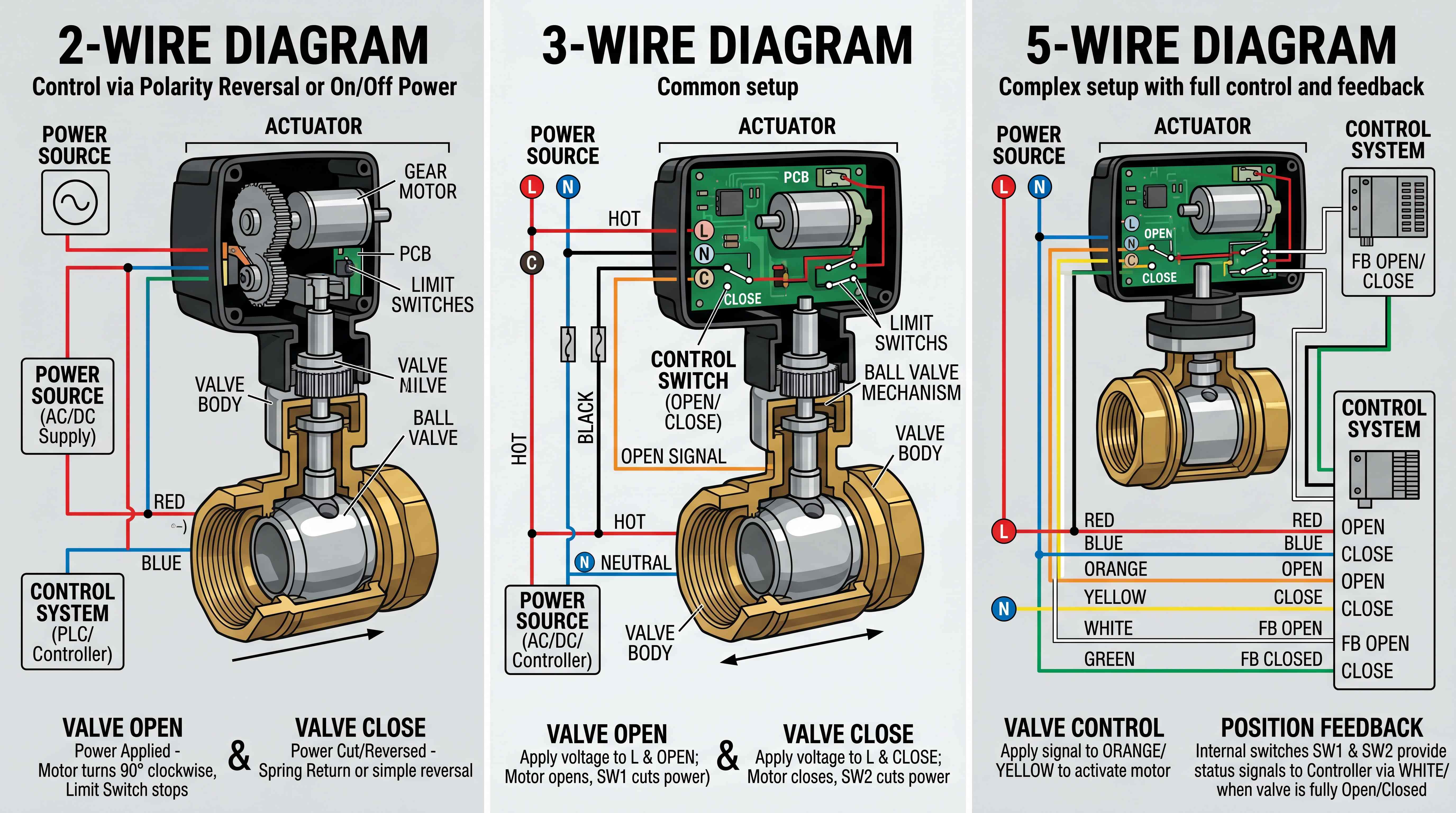
First, the control system sends a signal. This may come from a PLC, relay panel, emergency shutdown system, manual switch, timer or process controller. The signal may be 24VDC, 110VAC, 220VAC or another control voltage depending on the system design.
Second, the solenoid valve receives the signal. The solenoid valve changes the air path. In a double acting pneumatic actuator, it sends air to one side of the actuator to open the valve and air to the other side to close it. In a spring return pneumatic actuator, it sends air to move the valve in one direction, while the spring moves the valve back when air is released.
Third, compressed air enters the pneumatic actuator. Inside the actuator, air pressure pushes pistons or drives a mechanism such as rack and pinion or scotch yoke. This converts linear air movement into rotary motion.
Fourth, the actuator rotates the valve stem. The stem turns the ball inside the valve body. In most ball valves, 90-degree rotation changes the valve from open to closed or closed to open.
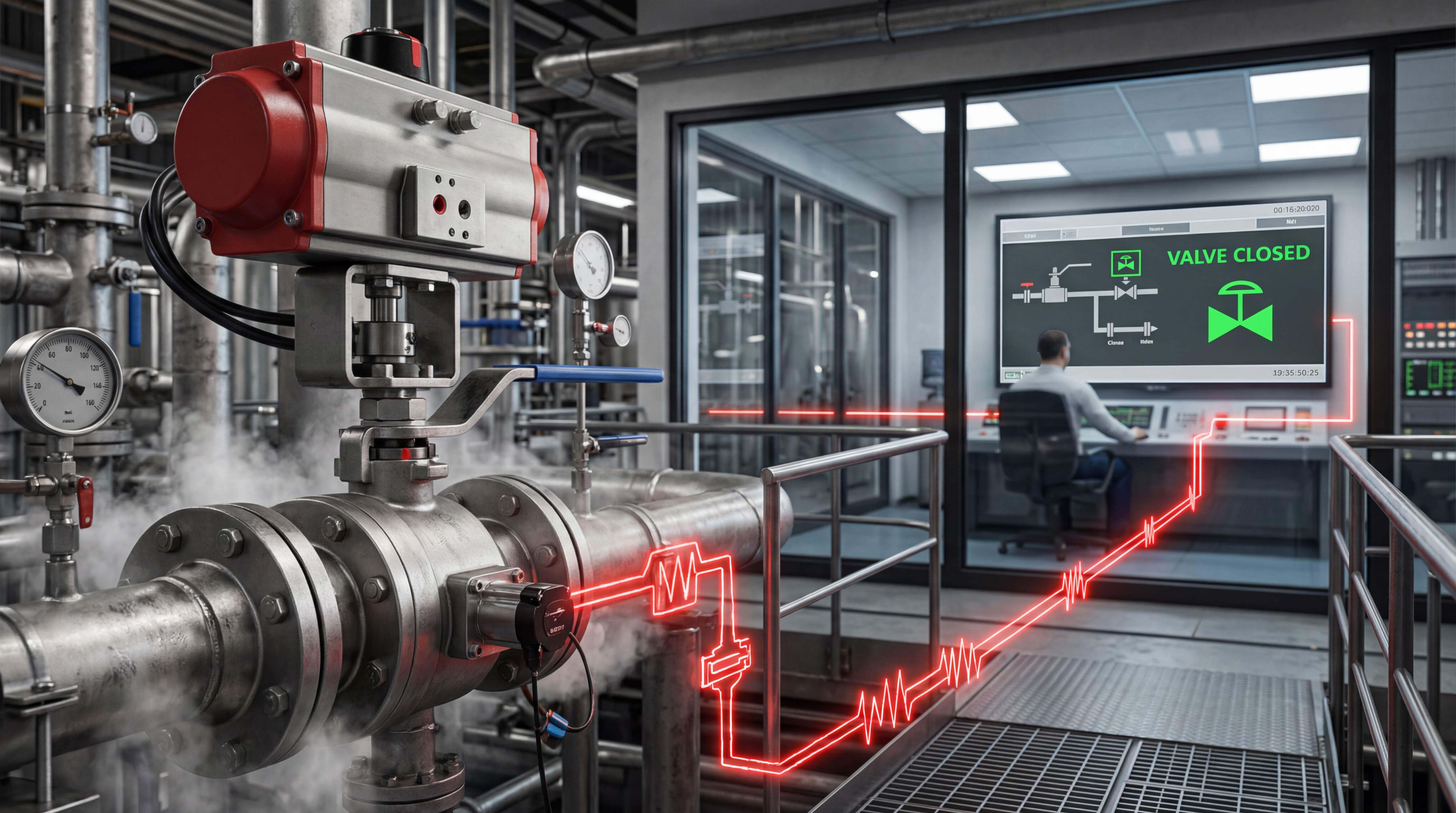
Fifth, feedback devices may confirm the result. A limit switch box can send open or closed signals back to the control system. A positioner can help the valve move to intermediate positions. A visual position indicator can help operators verify the valve state locally.
This chain shows why accessories matter. If any part of the chain is weak, the entire pneumatic ball valve assembly becomes unreliable. The valve may be strong, but the command may not reach it correctly. The actuator may be powerful, but the air may not be clean. The valve may move, but the control room may not know whether it reached the correct position.
Reliable pneumatic actuator control depends on every link in the chain.
Solenoid Valve for Pneumatic Actuator Control

A solenoid valve for pneumatic actuator control is the device that directs compressed air into and out of the actuator. It is one of the most important accessories in pneumatic valve automation.
The solenoid valve has an electrical coil and an internal spool or poppet mechanism. When the coil is energized, the internal air passage changes. This sends air to the actuator in a specific direction. When the coil is de-energized, the air path returns or changes again depending on the solenoid valve design.
For a pneumatic ball valve, the solenoid valve is usually selected according to actuator type, air supply pressure, control voltage, flow requirement, port size, mounting style and fail-safe function.
A double acting pneumatic actuator commonly uses a 5/2-way solenoid valve. This means the valve has five ports and two positions. It can send air to either side of the actuator, allowing air to open and air to close.
A spring return pneumatic actuator commonly uses a 3/2-way solenoid valve or a 5/2-way valve depending on actuator and system design. In a spring return arrangement, air moves the actuator in one direction, and the spring returns it when the air is released. This makes the solenoid valve part of the fail-safe behavior.
The solenoid valve must be sized properly. If the solenoid valve has too little flow capacity, the actuator may move slowly or fail to move under load. If the exhaust path is restricted, closing speed may be affected. If the solenoid coil voltage does not match the control system, the valve may not operate or may burn out.
A solenoid valve may look like a small component, but it is the command gateway for the entire pneumatic ball valve.
NAMUR Solenoid Valve: Why Standard Mounting Helps
A NAMUR solenoid valve is designed to mount directly onto a standardized interface on many pneumatic actuators. NAMUR mounting is common in industrial valve automation because it reduces tubing complexity and makes the assembly more compact.
Instead of using separate tubes between the solenoid valve and actuator ports, a NAMUR solenoid valve can be bolted directly to the actuator body. Internal port alignment allows air to pass between the solenoid and actuator. This simplifies installation and can reduce leak points.
NAMUR mounting also supports standardization. If many actuators in a plant use the same NAMUR interface, solenoid valve replacement becomes easier. Maintenance teams can stock fewer spare parts. Installation becomes cleaner and more consistent.
However, NAMUR compatibility does not remove the need for correct selection. The solenoid valve must still match actuator function, voltage, port configuration, air pressure, environmental protection and manual override needs. For outdoor, washdown, hazardous or corrosive areas, the solenoid enclosure and coil protection must be suitable.
Some NAMUR solenoid valves include manual override buttons. This allows technicians to operate the actuator locally during commissioning or troubleshooting. Manual override is useful, but it should be used carefully because it can move the valve unexpectedly.
A NAMUR solenoid valve is valuable because it simplifies pneumatic actuator control, but it must still be treated as a functional control device, not just a mounting accessory.
Double Acting Pneumatic Actuator Control

A double acting pneumatic actuator uses compressed air to move the actuator in both directions. Air opens the valve, and air closes the valve. This design is common in many pneumatic ball valve applications where air supply is reliable and no spring-return fail position is required.
In a typical double acting setup, a 5/2-way solenoid valve controls the air path. When the solenoid is energized, air enters one actuator port and exhausts from the other side. The actuator rotates the ball valve to one position. When the solenoid changes state, the air path reverses, and the actuator rotates the valve in the opposite direction.
Double acting actuators are efficient because they use air pressure for both opening and closing. They can provide strong torque in both directions. They are often used in process lines, utility systems, production equipment and systems where the valve should remain in its last position if air pressure is lost.
However, this “last position” behavior must be understood clearly. A double acting pneumatic actuator does not usually move to a defined safe position during air failure unless additional equipment is used. If air pressure is lost, the valve may stay where it is. That may be acceptable for some applications and unacceptable for others.
Double acting control also depends on stable air pressure. If plant air pressure drops, actuator torque drops. If the solenoid valve sticks, if air tubing leaks, or if exhaust ports are blocked, movement becomes unreliable.
A double acting actuator is a strong and practical solution when the system has good air supply and does not require spring-driven fail-safe movement. But it should not be selected when a defined fail open or fail close action is required without confirming the complete pneumatic control strategy.
Spring Return Pneumatic Actuator Control
A spring return pneumatic actuator uses compressed air in one direction and internal springs in the other direction. This design is widely used when the valve must move to a defined position if air pressure or control signal is lost.
For example, a chemical feed line may need a fail close ball valve. If air supply is lost, the spring closes the valve and stops chemical flow. A cooling line may require fail open behavior. If air or power is lost, the valve opens to maintain flow. The correct fail position depends on process safety.
Spring return actuators are often used with solenoid valves that release air when de-energized. When air pressure is applied, the actuator moves against the spring. When air is vented, the spring drives the actuator back. This gives the system mechanical fail-safe behavior.
The advantage is clear: the valve can return to a safe position without relying on electrical power or compressed air to move in the return direction. This is one reason spring return pneumatic actuator designs are common in emergency shutdown, chemical dosing, fuel control, drain control and safety-related systems.
But spring return sizing is more complex than many buyers expect. The spring must provide enough torque to move the valve under real process conditions. Air pressure must also be sufficient to compress the spring and move the valve in the opposite direction. Torque changes during the actuator stroke. The actuator supplier’s torque chart should be checked carefully.
A spring return actuator also stores mechanical energy. Manual override and maintenance must be handled safely. Technicians should understand the spring direction and fail position before working on the assembly.
Spring return control is powerful, but it must be selected and tested according to the real failure mode of the process.
Air Filter Regulator: Clean and Stable Air Is Not Optional

An air filter regulator is one of the most practical but often underestimated pneumatic ball valve accessories. It prepares the compressed air before it enters the solenoid valve or actuator.
Compressed air systems can contain moisture, oil, rust particles, dirt and pressure fluctuations. These contaminants may damage solenoid valves, actuator seals, positioners and other pneumatic components. If water enters the actuator, corrosion or freezing may occur. If dirt enters the solenoid valve, the spool may stick. If pressure is unstable, actuator torque becomes unstable.
The filter part removes particles and moisture. The regulator part sets the air pressure to a controlled value. In many pneumatic valve assemblies, the actuator is sized for a specific supply pressure, such as 5 bar or 6 bar. If the actual pressure is too low, the actuator may not produce enough torque. If pressure is too high, components may be stressed beyond their rating.
An air filter regulator is especially important in plants where compressed air quality is not carefully controlled. It is also important for outdoor installations, high-humidity areas, water treatment facilities and chemical plants.
The regulator should be installed where it is accessible for maintenance. Filters need draining or replacement. Pressure gauges should be readable. If the regulator is hidden behind equipment, maintenance teams may ignore it until valve problems appear.
A pneumatic actuator is only as reliable as the air supplied to it. Clean and stable air is not optional; it is part of the valve automation design.
Limit Switch Box: Proving the Valve Actually Moved

A limit switch box is used to detect and report valve position. It is usually mounted on top of the pneumatic actuator. Inside the box, mechanical cams or magnetic sensors detect actuator rotation. The device then sends open and closed signals to the control system.
This is critical because sending a command is not the same as confirming movement. The PLC may energize a solenoid valve, but the valve may fail to move due to low air pressure, a stuck actuator, a blocked valve, a broken coupling or a wiring issue. Without feedback, the control system may assume the valve is in the correct position when it is not.
A limit switch box provides position confirmation. For on-off ball valves, the most common feedback signals are fully open and fully closed. These signals can be used for interlocks, alarms, process sequencing and operator display.
For example, a pump may only start after the valve open signal is confirmed. A backwash process may only begin after several valves reach the correct positions. A chemical dosing system may require closed feedback before ending a batch. If the feedback is missing, the system can stop and alert operators.
Limit switch boxes can use mechanical switches, proximity sensors, inductive sensors or other technologies. The correct choice depends on environment, control voltage, hazardous area requirements and feedback type. Some boxes include visual indicators, making it easier for local operators to see valve position.
A limit switch box does not move the valve, but it tells the system whether movement succeeded. In automation, that information is often as important as the movement itself.
Valve Positioner: When Open-Close Control Is Not Enough

A valve positioner is used when the pneumatic ball valve needs modulating control rather than simple open-close operation. In on-off service, the valve only needs two positions. In modulating service, the valve may need to move to 25%, 50%, 75% or any intermediate position to regulate flow, pressure, level or temperature.
A valve positioner receives a control signal, often 4-20 mA, and compares the required position with the actual valve position. It then adjusts air pressure to the actuator until the valve reaches the commanded position.
For ball valves, positioners are often used with V-port ball valves or other control-oriented designs. A standard full-port ball valve is not usually ideal for precise throttling because its flow curve may be too nonlinear. But a V-port ball valve with a pneumatic actuator and positioner can become a practical flow control ball valve in many industrial systems.
Positioners improve accuracy and repeatability. They also help overcome friction, pressure effects and minor changes in valve load. Without a positioner, an actuator may not stop accurately at intermediate positions. With a positioner, the valve can follow a control signal more closely.
However, a positioner requires proper setup. It must be calibrated. Air supply must be clean. The actuator and valve must be suitable for modulation. The control loop must be tuned. If the positioner is installed on a valve that is not designed for control, the process may still be unstable.
A valve positioner is not needed for every pneumatic ball valve. It is needed when the process requires controlled positioning rather than simple open-close movement.
Visual Position Indicator: Simple but Valuable
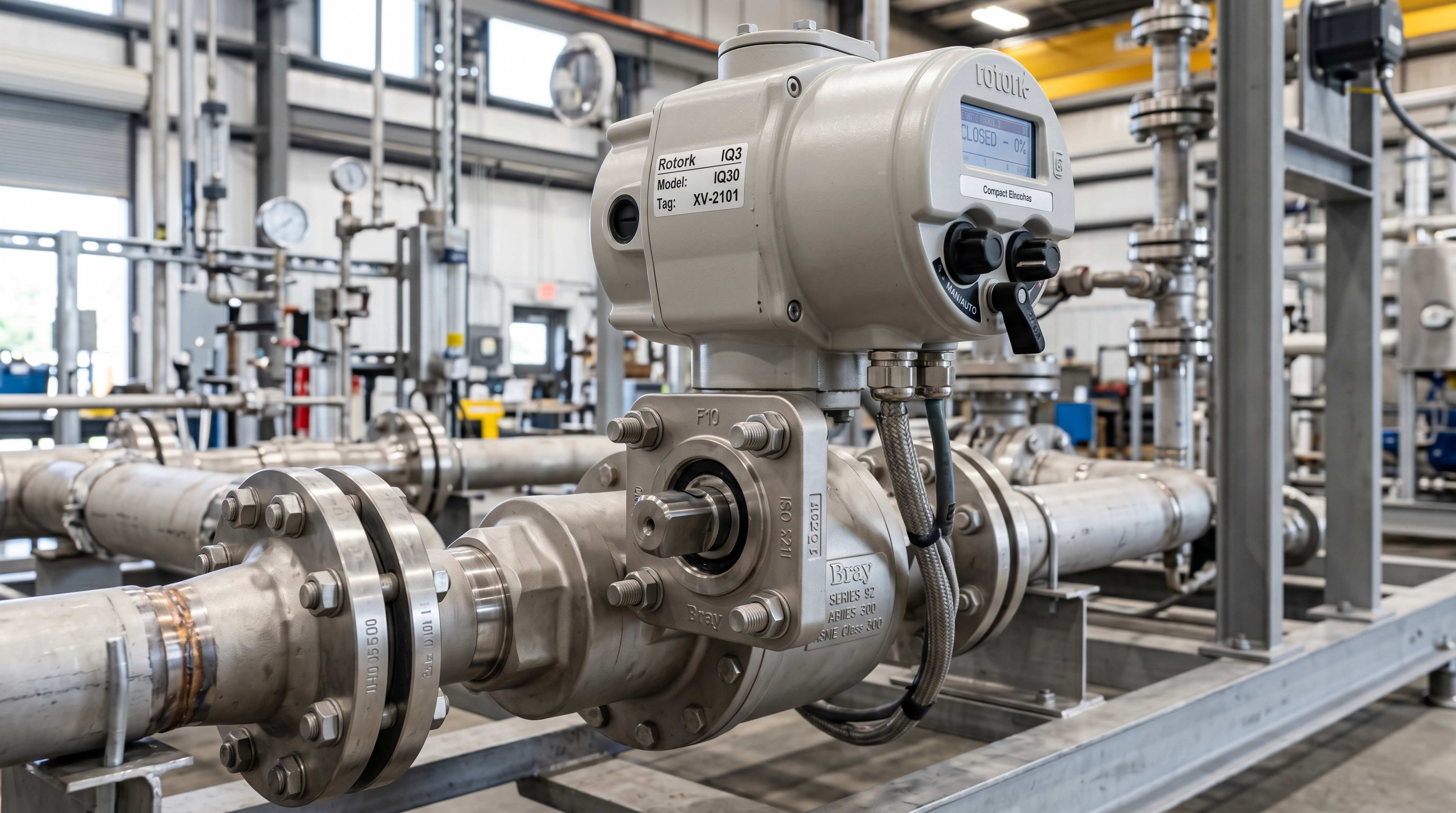
A visual position indicator shows the valve position locally. It may be a small dome indicator on top of the actuator, a pointer, a color window or another mechanical display. On a pneumatic ball valve, this is a simple but valuable accessory.
Operators and maintenance personnel often need to verify valve position in the field. A visual indicator makes this faster. Instead of tracing control signals or guessing from pipe behavior, they can look at the actuator and see whether the valve is open or closed.
Visual indication is especially useful during commissioning, maintenance, troubleshooting and manual operation. If the control room shows one status but the local indicator shows another, technicians can identify a feedback or calibration issue.
For three-way valves, visual indication must be handled carefully. A simple open/closed indicator may not be enough. The indicator should correspond to actual flow paths. If the valve switches between process, bypass and drain, labels should be clear.
A visual indicator is not a substitute for electrical feedback, but it is an important human-facing tool. In industrial plants, good local visibility reduces mistakes and speeds up troubleshooting.
Speed Control and Exhaust Management
Some pneumatic ball valve assemblies include speed control devices. These may be installed on actuator ports, solenoid valve exhaust ports or air lines. Their purpose is to control how fast the actuator opens or closes.
Fast actuation is useful in many systems, but too much speed can create problems. A valve that closes too quickly may cause water hammer in liquid systems. A valve that opens too quickly may shock downstream equipment. A fast exhaust may create noise or unsafe air discharge. A heavy actuator moving quickly may stress mounting hardware.
Speed controls allow technicians to adjust opening and closing time. In a water system, slower closing may protect piping. In a process system, controlled movement may improve sequencing. In a safety system, speed must be balanced with required response time.
Exhaust silencers may also be used to reduce noise. However, exhaust devices can become clogged, especially in dirty environments. A clogged exhaust can slow actuator movement or prevent proper operation. Maintenance teams should inspect these small parts during troubleshooting.
Actuator speed is not only a comfort issue. It affects process stability, mechanical stress and safety. Pneumatic valve automation should include speed control when fast movement could create risk.
Manual Override and Local Operation
Manual override allows local operation of the pneumatic actuator or solenoid valve. This is important during commissioning, maintenance and emergency troubleshooting.
A solenoid valve may include a manual override button or screw. Pressing it shifts the air path without an electrical signal. This can help technicians test actuator movement, confirm air supply and diagnose wiring problems.
Some pneumatic actuators may also use manual override mechanisms, especially larger actuators or spring return designs. Manual gear overrides may be used when local operation is required during air failure.
However, manual override must be used carefully. Moving a valve manually can affect the process. Opening a chemical line, closing a cooling line or changing a bypass valve can create safety risks if the process is running. Operators should follow site procedures.
Manual override should also be accessible. If the actuator is installed too close to a wall, pipe rack or panel, the override may be impossible to reach. Good valve assembly design includes enough space for local operation.
A manual override is not only a convenience. It is part of maintenance strategy and emergency planning.
Accessory Selection for Hazardous and Outdoor Areas
Pneumatic valve accessories must match the installation environment. This is especially important in outdoor, washdown, corrosive or hazardous areas.
For outdoor installations, solenoid coils, limit switch boxes and positioners need suitable enclosure protection. Cable entries and conduit seals must prevent water ingress. Air lines should be protected from UV damage, mechanical impact and freezing.
In washdown environments, water and cleaning chemicals may reach the actuator and accessories. Stainless steel hardware, sealed enclosures and proper cable glands may be required. A valve body may survive washdown while the solenoid coil or limit switch box fails if not protected.
In corrosive areas, chemical vapor can attack aluminum housings, painted surfaces, fasteners and wiring components. Material selection should include accessories, not only the valve body.
In hazardous areas, electrical accessories may require explosion-proof, intrinsically safe or other certified designs depending on area classification. Even if the actuator itself is pneumatic, the solenoid valve and limit switch box are electrical devices. They must be selected according to site safety requirements.
The environment can turn a good component into a weak point. Accessory selection should always consider where the valve will actually be installed.
Common Pneumatic Ball Valve Accessory Mistakes
One common mistake is selecting the actuator and valve correctly but using a solenoid valve with the wrong port configuration. A double acting actuator and spring return actuator often need different solenoid logic.
Another mistake is using the wrong solenoid voltage. A 24VDC control system cannot directly operate a 110VAC coil unless a proper relay or interface is used. Wrong voltage can prevent operation or burn the coil.
A third mistake is ignoring air flow capacity. A small solenoid valve may technically connect to the actuator but may move it too slowly or unreliably.
A fourth mistake is skipping the air filter regulator. Dirty or wet air can damage solenoids, positioners and actuator seals.
A fifth mistake is installing a limit switch box but not calibrating the cams correctly. The control system may receive false open or closed signals.
A sixth mistake is using a positioner on a valve that is not suitable for modulating control. The positioner may move the actuator, but the flow response may still be unstable.
A seventh mistake is assuming NAMUR mounting means everything is compatible. NAMUR helps mounting, but voltage, function, air path and environment must still be checked.
An eighth mistake is ignoring exhaust and speed control. A valve may close too quickly and create water hammer, or too slowly and disrupt the process sequence.
A ninth mistake is forgetting maintenance access. Accessories installed in tight spaces may be hard to replace or adjust.
Most accessory problems are preventable when the pneumatic ball valve is specified as a complete control assembly rather than separate parts.
How to Specify a Complete Pneumatic Ball Valve Assembly
A complete specification should start with the valve function. Is the ball valve used for isolation, diverting, mixing, bypass, emergency shutdown or modulating control?
Next, define actuator type. Choose a double acting pneumatic actuator if air-open and air-close operation is acceptable. Choose a spring return pneumatic actuator if fail open or fail close behavior is required.
Then specify the solenoid valve. Confirm port configuration, voltage, mounting type, manual override, enclosure rating and flow capacity. If using NAMUR solenoid valve mounting, confirm compatibility with the actuator.
After that, specify air preparation. Include an air filter regulator when air quality or pressure stability is important. Define required supply pressure and pressure gauge needs.
Then define feedback. If the control system needs position confirmation, specify a limit switch box, proximity sensor or feedback module. Confirm output type and control system compatibility.
If modulating control is needed, specify a valve positioner. Confirm control signal, actuator compatibility, air supply requirement and calibration procedure.
Next, consider accessories such as speed controls, exhaust silencers, local indicators and manual overrides.
Then review environment. Indoor, outdoor, washdown, hazardous and corrosive locations require different accessory protection.
Finally, define testing. The assembly should be tested for open-close movement, fail-safe action, feedback signals, air leakage and response time before installation.
This specification method turns pneumatic valve automation into a controlled engineering package.
Maintenance Strategy for Pneumatic Valve Accessories
Maintenance should include more than the valve body and actuator. Accessories need routine inspection.
Solenoid valves should be checked for coil condition, manual override function, air leakage and spool response. If the solenoid sticks, the actuator may not move even when the control signal is correct.
Air filter regulators should be checked for pressure setting, filter contamination and moisture accumulation. A clogged filter can reduce air flow. Water in the bowl may indicate poor compressed air quality.
Limit switch boxes should be checked for correct open and closed feedback. Vibration, actuator replacement or cam movement can change switch adjustment.
Positioners should be calibrated and checked for stable response. Dirty air can cause positioner problems. Control signal wiring should also be inspected.
Tubing and fittings should be checked for leaks, cracks, loose connections and damage. Small air leaks can reduce actuator speed and waste compressed air.
Exhaust silencers and speed controls should be checked for blockage. A blocked exhaust may cause slow or incomplete movement.
Visual indicators should be checked against actual valve position. If the indicator is wrong, operators may make incorrect decisions.
Good maintenance keeps the whole pneumatic control chain reliable, not just the valve.
Final Thoughts
A pneumatic ball valve is not simply a valve with an air actuator. It is a complete control assembly. The actuator provides torque, but accessories provide command, air quality, feedback, positioning, speed control and maintenance visibility.
A solenoid valve for pneumatic actuator control converts electrical signals into air movement. A NAMUR solenoid valve can simplify mounting and reduce tubing. An air filter regulator protects the actuator and control components by supplying clean, stable air. A limit switch box confirms whether the valve reached the commanded position. A valve positioner enables modulating control when intermediate positioning is required. Speed controls, exhaust silencers, visual indicators and manual overrides complete the practical field package.
When these accessories are selected correctly, pneumatic valve automation becomes reliable and easy to troubleshoot. When they are ignored, even a good valve and actuator can fail in operation.
The best approach is to specify the pneumatic ball valve as a system: valve body, actuator, solenoid valve, air preparation, feedback, position control, mounting, environment and maintenance access. That system-level thinking is what turns a mechanical valve into dependable industrial flow control.
Focused FAQ
What accessories are needed for a pneumatic ball valve?
Common pneumatic ball valve accessories include a solenoid valve, air filter regulator, limit switch box, valve positioner, visual position indicator, speed control valves, exhaust silencers, tubing, fittings and manual override devices.
What does a solenoid valve do on a pneumatic actuator?
A solenoid valve controls the air path to the pneumatic actuator. It converts an electrical signal from a PLC, relay or switch into compressed air movement that opens or closes the ball valve.
What is a NAMUR solenoid valve?
A NAMUR solenoid valve is designed to mount directly onto a standardized pneumatic actuator interface. It reduces external tubing and makes pneumatic actuator control cleaner and more compact.
What is the difference between a double acting pneumatic actuator and a spring return pneumatic actuator?
A double acting pneumatic actuator uses air to open and air to close. A spring return pneumatic actuator uses air in one direction and internal springs to return the valve to a defined fail position.
Why is an air filter regulator important?
An air filter regulator removes contaminants and controls air pressure before air reaches the actuator or solenoid valve. Clean and stable air helps prevent sticking, seal damage, low torque and unreliable valve movement.
What does a limit switch box do?
A limit switch box detects valve position and sends open or closed feedback signals to the control system. It helps confirm that the pneumatic ball valve actually reached the commanded position.
When is a valve positioner needed?
A valve positioner is needed when the pneumatic ball valve must move to intermediate positions for modulating control. It is commonly used with V-port ball valves and 4-20 mA control signals.
Can a pneumatic ball valve work without a limit switch box?
Yes, a pneumatic ball valve can open and close without a limit switch box. However, the control system will not have direct confirmation of valve position unless another feedback method is used.
Why does pneumatic actuator air pressure matter?
Pneumatic actuator output torque depends on air pressure. If air pressure is too low, the actuator may not have enough torque to move the valve reliably under process conditions.
What is the most common problem in pneumatic valve automation?
Common problems include wrong solenoid valve selection, poor air quality, low air pressure, air leaks, misadjusted limit switches, blocked exhaust ports, incorrect fail-safe logic and lack of maintenance access.
#PneumaticBallValveAccessories #SolenoidValveForPneumaticActuator #LimitSwitchBox #ValvePositioner #AirFilterRegulator #NAMURSolenoidValve #PneumaticActuatorControl #SpringReturnPneumaticActuator #DoubleActingPneumaticActuator #PneumaticValveAutomation #BallValveAutomation #ValveAutomation #IndustrialComponents #FlowControl #ProcessAutomation