Automated Ball Valve Troubleshooting: Leakage, Sticking, Slow Actuation and Maintenance Strategy
Why Automated Ball Valve Problems Are Rarely Caused by One Component Alone
An automated ball valve may look like a compact assembly: a ball valve body, an actuator, a few wires or air tubes, and sometimes a feedback device. Because the assembly looks simple, many people also troubleshoot it in a simple way. If the valve does not move, they blame the actuator. If the pipeline leaks, they blame the valve seat. If the control panel does not show the correct status, they blame the limit switch.
In real industrial systems, automated ball valve troubleshooting is usually more complex.
A ball valve may fail to close because the actuator is undersized, but it may also fail because the media left deposits on the ball, the seat swelled after chemical exposure, the air pressure dropped, the electric supply voltage is unstable, the coupling slipped, the limit switch was misadjusted, or the valve was installed under pipe stress. A valve may leak because the seat is worn, but it may also leak because the actuator never reaches full closed position. A pneumatic ball valve problem may appear to be mechanical, but the actual cause may be wet compressed air or a clogged exhaust port. An electric ball valve problem may appear to be electrical, but the real issue may be excessive breakaway torque caused by a valve that has not moved for months.
This is why industrial valve troubleshooting should follow a system-level method. The valve, actuator, media, control signal, power supply, air supply, position feedback, mounting hardware and maintenance history should all be considered together.
The goal is not only to make the valve move again. The goal is to understand why the problem happened, prevent repeated failure, and improve long-term valve maintenance strategy.

Begin with the Symptom, Not the Assumption
The first step in automated ball valve troubleshooting is to describe the symptom accurately. Do not begin by assuming the actuator is bad or the valve body is defective. Begin with what the system is actually doing.
Is the valve not moving at all? Does it move slowly? Does it move only in one direction? Does it stop halfway? Does it reach open position but not closed position? Does the actuator move but the valve stem does not? Does the valve appear closed but still leak? Does the control room show open while the field indicator shows closed? Does the problem happen every cycle or only after long shutdown? Does it happen under pressure but not during bench testing?
These details matter because different symptoms point to different causes.
A valve that does not move at all may have no power, no air, a failed solenoid, a burned motor, broken wiring or excessive breakaway torque. A valve that moves slowly may have low air pressure, blocked exhaust, undersized solenoid valve, weak voltage, damaged actuator gears or heavy media deposits. A valve that leaks after closing may have seat damage, incomplete travel, debris on the sealing surface or incorrect actuator stop setting. A valve position feedback fault may come from a limit switch, cam adjustment, wiring problem, PLC input issue or mechanical coupling slip.
Accurate symptom definition saves time. It prevents replacing good components and missing the real root cause.
Check the Process Condition Before Touching the Actuator
Before opening an actuator cover, replacing a solenoid valve or adjusting limit switches, check the process condition. Many automated ball valve problems are not caused by the actuator. They are caused by the fluid system.
The media may be different from what the valve was originally selected for. A valve designed for clean water may now handle wastewater, chemical residue, glycol, sticky liquid or solids. A stainless steel ball valve may be installed in a corrosive line without compatible seat materials. A PVC valve may be exposed to temperature or pressure beyond its safe range. A valve that was selected for normal flow may experience pressure spikes or water hammer.
Pressure matters. A ball valve may turn easily when the line is depressurized but require much higher torque under full working pressure. In floating ball designs, pressure can push the ball against the seat and increase operating torque. If the actuator was selected with little safety margin, the valve may fail only under real process pressure.
Temperature also matters. High temperature can soften seats or increase packing friction. Low temperature can increase media viscosity or make seals less flexible. Cleaning cycles may expose the valve to fluids and temperatures that are more severe than normal operation.
Deposits are another common cause. Minerals, scale, crystallized chemicals, sludge, fibers or biological growth can make the ball valve stuck or increase torque. If the valve stays in one position for a long time, static friction and buildup can become worse.
A good troubleshooting process always asks: has the process changed since the valve was installed?
Ball Valve Leakage: Seat Damage, Debris or Incomplete Closing

Ball valve leakage is one of the most common maintenance complaints. It may appear as internal leakage through the valve when it should be closed, or external leakage around the stem, body joint or flange connection.
Internal leakage usually means the valve is not sealing properly. The cause may be seat wear, seat deformation, chemical attack, erosion, scratches on the ball, trapped debris or incomplete closing. In automated valves, incomplete closing is especially important. The actuator may stop before the ball reaches the fully closed position, leaving a small flow path.
A valve can appear closed from the control panel while not being mechanically closed. This can happen when limit switch feedback is misadjusted. The switch may report “closed” before the ball is fully seated. It can also happen when the actuator stop position is wrong or the coupling between actuator and stem has slipped.
Debris is another frequent cause. In water treatment, wastewater, chemical processing and utility systems, particles may become trapped between the ball and seat. Even a small particle can prevent tight shut-off. If the valve is repeatedly forced closed on debris, the seat may become damaged.
Seat material compatibility is also critical. A seat material that swells, hardens or cracks after media exposure will not seal reliably. A chemical resistant valve must be selected as a complete material system, not only by body material.
External leakage around the stem often relates to stem packing. Packing may loosen, wear or degrade. External leakage at flanges may be caused by gasket problems, pipe stress, incorrect tightening or thermal cycling.
The key to ball valve leakage diagnosis is to separate sealing failure from actuator positioning failure. Replacing the valve seat will not solve the problem if the actuator never fully closes the valve.
Ball Valve Stuck: Why the First Movement Can Be the Hardest

A ball valve stuck in open or closed position often creates panic because the actuator may hum, stall, alarm or fail to move. This problem is closely related to breakaway torque.
Breakaway torque is the torque needed to start valve movement from a stationary position. For many ball valves, this first movement is harder than the rest of the stroke. The ball is pressed against the seat, the stem packing has static friction, and the media may have created deposits. If the valve has not operated for a long time, the starting torque can increase significantly.
A ball valve stuck problem may be caused by several conditions. The actuator may be undersized. The valve may be exposed to pressure higher than expected. The media may be sticky, crystallized or dirty. The seat material may have swollen. Corrosion may have developed around the stem. The coupling may be misaligned. Pipe stress may distort the valve body. The actuator may not receive enough air pressure or voltage.
Manual operation can help diagnose the issue, but it must be done safely. If the valve is under pressure, contains hazardous media or belongs to an automated sequence, operators should follow site procedures. Forcing a stuck valve with excessive manual force can damage the stem, seats or actuator coupling.
If a valve repeatedly sticks after long idle periods, the solution may not be only a larger actuator. The system may need periodic exercise cycles, better media flushing, improved material selection, a different seat design, filtration upstream, or a maintenance procedure that prevents buildup.
A stuck valve is often a sign that the process and the automation design are not fully matched.
Slow Valve Actuation: Air, Power, Exhaust and Mechanical Resistance
Slow valve actuation is a useful warning sign. The valve still moves, but something in the system is limiting movement speed. If ignored, slow movement can later become complete actuator failure.
For pneumatic valves, slow movement is often caused by low air pressure, restricted air flow, undersized solenoid valves, clogged filters, blocked exhaust ports, long tubing runs, small tubing diameter, damaged actuator seals or contaminated compressed air. A pneumatic actuator depends on both pressure and flow. Pressure provides force, but flow determines how quickly the actuator fills and exhausts.
An air filter regulator may be clogged. A regulator may be set too low. The plant air supply may drop during peak demand. A silencer on the exhaust port may be blocked by dirt. A speed control valve may be adjusted too tightly. Tubing may be kinked or leaking.
For electric valves, slow movement may be caused by low voltage, voltage drop over long cables, weak power supply, motor wear, gearbox damage, excessive torque demand or control board issues. A 24V electric actuator may work near the power supply but move slowly at the end of a long cable if the wire size is too small.
Mechanical resistance also causes slow actuation. Deposits, damaged seats, tight stem packing, misaligned brackets or pipe stress can increase torque. The actuator may still move the valve, but only slowly and with strain.
Slow movement should be documented. If normal travel time is five seconds and it becomes twelve seconds, that change matters. Travel time trending can help detect valve maintenance issues before complete failure.
Actuator Failure: Electrical, Pneumatic or Mechanical?

Actuator failure is often used as a general phrase, but it should be divided into electrical failure, pneumatic failure and mechanical failure.
In electric actuators, electrical failure may involve power supply loss, blown fuses, wrong voltage, burned motor, damaged control board, faulty capacitor, failed relay, limit switch failure or water ingress. Mechanical failure may involve stripped gears, broken coupling, worn output shaft or jammed gearbox.
In pneumatic actuators, failure may involve no air supply, low air pressure, solenoid valve failure, air leakage, damaged piston seals, broken springs, blocked exhaust, corrosion inside the actuator or mechanical binding. A spring return pneumatic actuator may fail if the spring is broken or if the spring torque is no longer enough to return the valve under load.
Actuator failure can also be caused by the valve. An actuator may burn out because the valve torque is too high. A pneumatic actuator may stall because the valve is stuck. A coupling may fail because the actuator is oversized and applies excessive force. In these cases, replacing the actuator without addressing the valve problem will lead to repeated failure.
A practical test is to separate actuator movement from valve movement when safe and possible. If the actuator operates normally when disconnected from the valve, the valve torque or coupling may be the problem. If the valve turns smoothly by hand but the actuator fails, the actuator or control system may be the problem.
The point is simple: actuator failure should not be diagnosed in isolation.
Electric Ball Valve Problem Diagnosis

An electric ball valve problem often begins with power and wiring. The first questions should be basic: is the correct voltage present at the actuator? Is the voltage AC or DC as required? Is polarity correct for DC models? Are open and close command wires connected correctly? Is the controller output capable of supplying the required current? Are fuses intact? Is the actuator receiving the command signal?
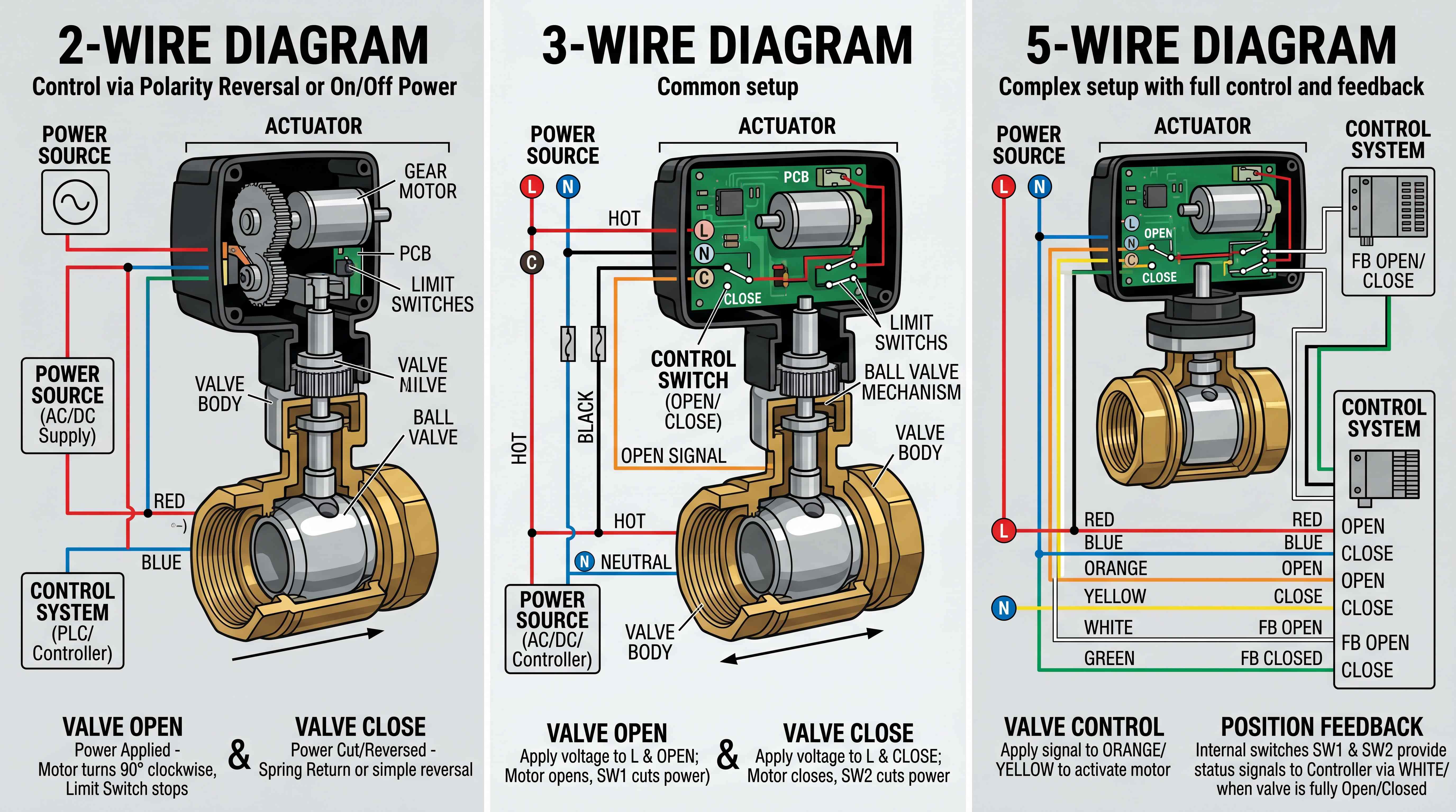
Wire colors should not be trusted without a wiring diagram. Different manufacturers use different color coding. A 2-wire motorized ball valve may require reverse polarity, while another 2-wire valve may use power-on auto-return logic. A 3-wire actuator may have common, open and close wires. A 5-wire actuator may include feedback wires. Misunderstanding the wiring type can create false failure diagnosis.
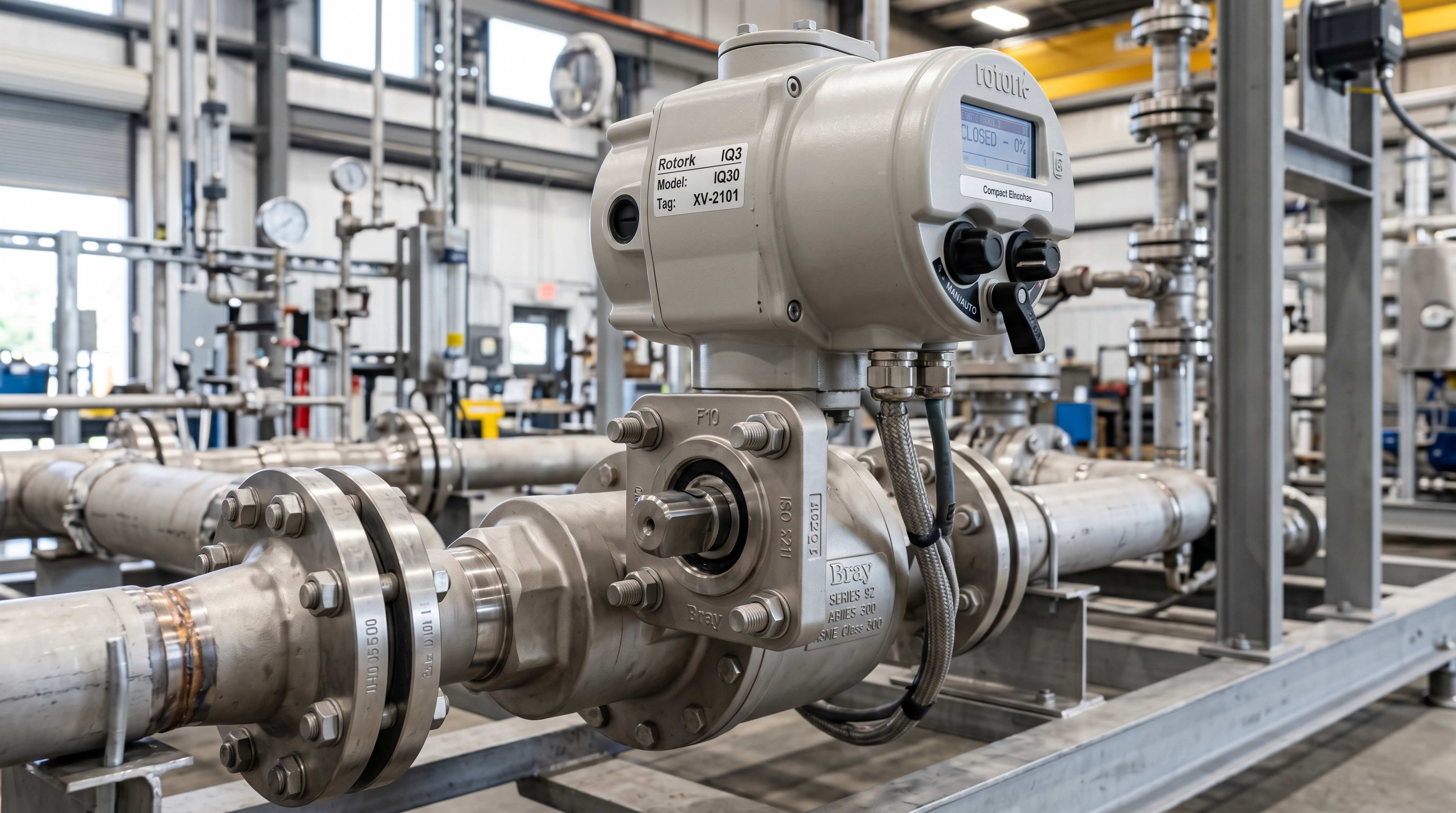
Limit switches inside electric actuators can also cause problems. If an internal limit switch fails or is misadjusted, the motor may stop early or not stop correctly. Some actuators include torque protection, thermal protection or overload protection. These may trip if the valve torque is too high.
Moisture is a major issue. Outdoor, washdown or humid environments can allow water into cable glands, actuator covers or conduit entries. Water can damage the control board and create intermittent faults.
For troubleshooting, check command voltage, actuator response, travel time, feedback signals and manual override. If the actuator has a manual override and the valve turns normally by hand, the electrical control side may be the issue. If manual operation is difficult, the valve may be mechanically stuck.
Electric ball valve troubleshooting should combine electrical testing with mechanical verification.
Pneumatic Ball Valve Problem Diagnosis

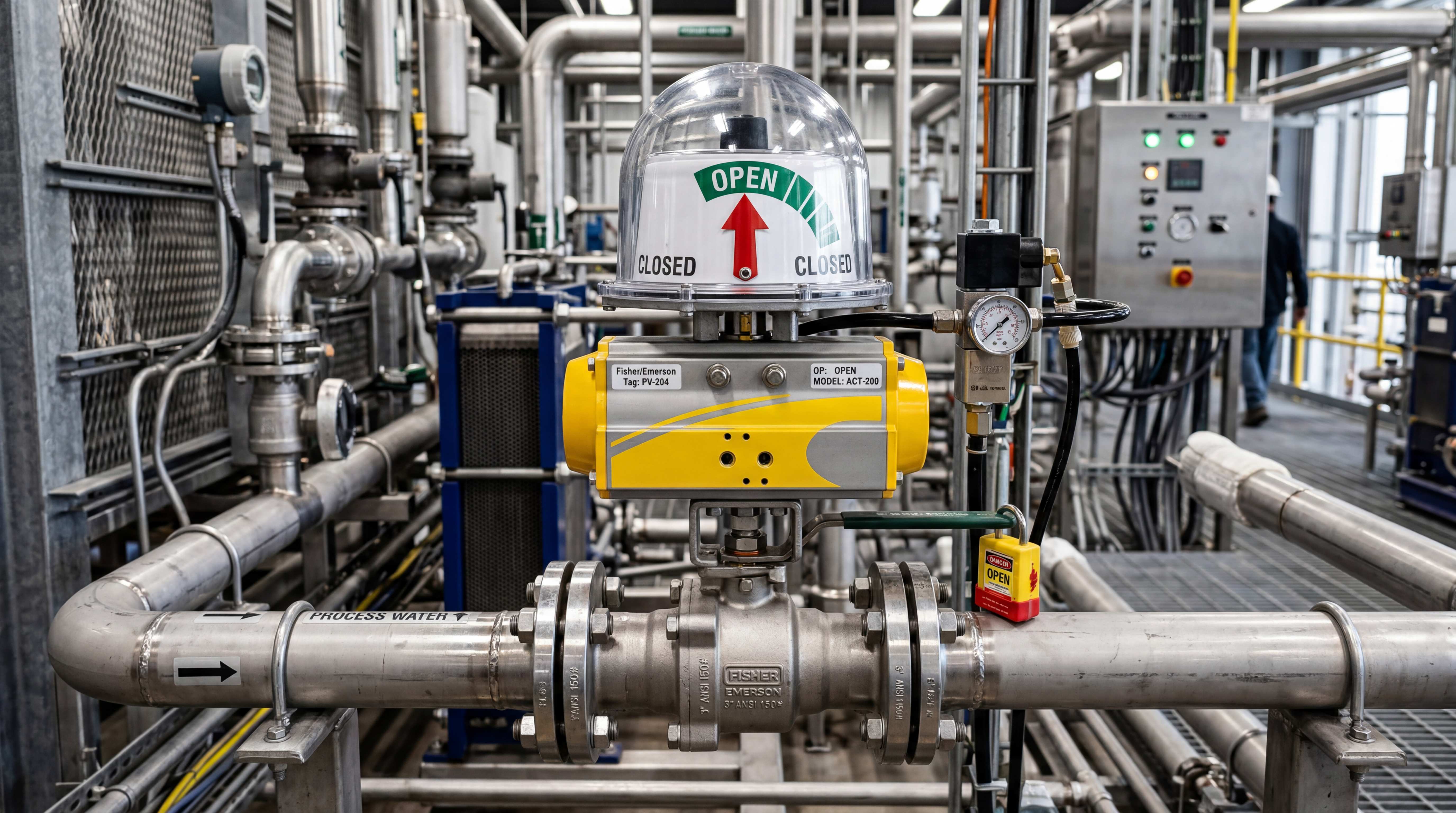
A pneumatic ball valve problem often starts with compressed air. Check whether air pressure is available at the actuator, not only at the compressor. The pressure at the valve location may be lower due to regulator settings, leaks, clogged filters, undersized tubing or simultaneous air demand.
Next, check the solenoid valve. Does the coil receive the correct voltage? Does it shift when energized? Does the manual override operate the actuator? Is the solenoid valve the correct type for double acting or spring return operation? Are the ports connected correctly? Are exhaust ports blocked?
Then check the air filter regulator. A clogged filter can restrict air flow. Water in the filter bowl may indicate poor air quality. A regulator set too low can cause insufficient actuator torque. Oil, rust and dirt in compressed air can damage solenoid valves and actuator seals.
Check tubing and fittings for leaks. Even small leaks can slow actuation and reduce available torque. Listen for air leakage during operation. Use approved leak detection methods when needed.
Check actuator behavior. Does it move both directions? Does it move one direction only? Does a spring return actuator return fully when air is vented? Does the actuator stop halfway? Does it move smoothly or jerk?
Finally, check the valve. A pneumatic actuator may be healthy but unable to move a valve with excessive torque. If possible, compare actuator operation disconnected from the valve and valve operation by manual force.
Pneumatic valve automation depends on clean air, correct solenoid logic, adequate pressure and proper mechanical load.
Valve Position Feedback Fault: When the Signal Lies
A valve position feedback fault can be confusing because the valve and actuator may be moving correctly while the control system displays the wrong status. Or the control system may show correct feedback while the valve is not actually in the correct position.
Feedback systems include limit switch boxes, proximity sensors, internal actuator switches, position transmitters and smart positioners. These devices must be adjusted and wired correctly.
One common issue is cam misadjustment in a limit switch box. The cam may activate the closed switch before the valve is fully closed. The PLC receives a closed signal, but the valve still leaks. Another issue is loose coupling. The actuator indicator may rotate, but the valve stem may not follow fully. Feedback attached to the actuator then reports actuator position, not actual valve position.
Wiring problems can also create false signals. A broken wire, loose terminal, incorrect PLC input configuration or wrong voltage can cause missing feedback. Some feedback contacts are dry contacts, while others provide powered signals. Mixing these can damage inputs or create unreliable status.
For modulating valves, position feedback may drift or require calibration. A valve positioner may show 50%, but the real flow may not match due to valve wear, nonlinear characteristics or mechanical backlash.
Feedback should be verified against actual valve movement. Do not rely only on the control screen. Check local visual indicators, stem position, flow behavior and physical valve state when safe.
A feedback signal is useful only when it represents the real valve position.
Mounting, Coupling and Alignment Problems
The mechanical interface between actuator and valve is a common hidden failure point. The actuator may produce enough torque, and the valve may be in good condition, but poor mounting can create repeated problems.
A misaligned mounting bracket can push the valve stem sideways. This increases friction and may damage stem packing. A weak bracket can flex during operation, wasting actuator torque and causing inconsistent travel. A loose coupling can create backlash or slip. A poorly machined coupling can bind the stem. Incorrect ISO 5211 mounting components can make the assembly appear connected while creating mechanical stress.
Mounting problems often show up as slow movement, high torque, incomplete travel, repeated actuator overload, inconsistent feedback or stem leakage. They may be more obvious after several months of operation because vibration and repeated cycling loosen hardware.
Direct mount assemblies reduce some bracket issues, but they can create other problems if actuator weight, heat or clearance is not considered. Bracket-mounted assemblies provide flexibility but require stronger alignment control.
During troubleshooting, inspect mounting bolts, bracket rigidity, coupling engagement, stem position and actuator alignment. Marking the actuator output and valve stem can help identify slip during operation.
An automated valve assembly is a torque path. If the torque path is weak, the valve will not operate reliably.
Media Deposits, Scaling and Contamination
Media contamination is a major reason automated ball valves fail over time. Clean test water in a factory does not represent every real application.
In water systems, mineral scale can build up around the ball and seats. In wastewater systems, solids and fibers can interfere with sealing. In chemical systems, crystallization can lock the ball in position. In food or process systems, product residue can dry or harden. In compressed air systems, oil and water can affect seals. In slurry service, abrasive particles can wear seats and ball surfaces.
Deposits can cause several symptoms: ball valve stuck, slow valve actuation, leakage, increased torque, incomplete closing and actuator overload. If deposits are severe, replacing the actuator will not solve the issue.
Prevention may include upstream filtration, periodic flushing, suitable material selection, full port design, proper seat material, regular exercise cycles, cleaning procedures and correct valve orientation. In some severe services, a ball valve may not be the best valve type.
Maintenance teams should inspect failed valves for evidence of deposits. The appearance of the ball, seats and body cavity can reveal whether the problem is caused by media rather than automation hardware.
The valve’s internal condition tells the history of the process.
Preventive Valve Maintenance: Exercise, Inspect and Record
Valve maintenance should be planned before failure. Automated valves are often installed in places where operators do not touch them daily, so problems may remain hidden until the valve is needed.
Exercise cycles are useful for valves that normally stay open or closed for long periods. Periodic movement helps reduce sticking and confirms actuator function. The frequency depends on process risk, media and site practice. A backup valve that never moves may not work when finally needed.
Inspection should include visual checks for leakage, corrosion, loose hardware, damaged cables, air leaks, moisture ingress, broken indicators and abnormal noise. For pneumatic valves, inspect air filter regulators, tubing, solenoid valves and exhaust silencers. For electric valves, inspect cable glands, enclosure seals, wiring terminals and manual override function.
Recordkeeping is important. Travel time, failure alarms, feedback faults, air pressure settings and maintenance actions should be documented. If a valve’s travel time gradually increases, that trend may predict future failure. If the same actuator fails repeatedly, the root cause may be valve torque, media deposits or incorrect sizing.
Preventive maintenance is not just cleaning and tightening. It is a way to detect changes before they become downtime.
Troubleshooting Method: A Practical Sequence
A structured troubleshooting sequence helps avoid guesswork.
First, confirm safety. Identify the media, pressure, temperature and process consequences before touching the valve. Lockout and site procedures may be required.
Second, verify the command. Check whether the control system is actually sending an open or close signal.
Third, verify energy supply. For electric valves, check voltage and current. For pneumatic valves, check air pressure and flow at the actuator.
Fourth, observe movement. Does the actuator move? Does the valve stem move? Does the movement reach full travel? Is the movement slow, noisy or uneven?
Fifth, compare feedback. Check control room status, local indicator, limit switch box and actual valve position.
Sixth, separate actuator and valve if safe. Determine whether the actuator can move without the valve and whether the valve can move manually.
Seventh, inspect mechanical connection. Check bracket, coupling, stem, mounting bolts and alignment.
Eighth, inspect process-related causes. Look for deposits, corrosion, seat swelling, debris, pressure effects and temperature changes.
Ninth, identify root cause before replacing parts. A failed actuator may be the result, not the cause.
Tenth, document the repair and update maintenance practices if needed.
This method turns automated ball valve troubleshooting into a repeatable process rather than trial and error.
When Replacement Is Better Than Repair
Not every automated ball valve should be repaired. Sometimes replacement is safer and more economical.
Replace the valve if seats are severely damaged, the ball is scratched or corroded, the body is cracked, the stem is bent, the valve material is incompatible with the media, or leakage creates safety risk. Replace the actuator if the motor is burned, gears are stripped, springs are broken, housing is corroded, water has damaged electronics, or spare parts are unavailable.
Replace the complete assembly if the original selection was wrong. For example, a standard ball valve used for throttling may repeatedly fail; replacing only the seats does not solve the control problem. A low-torque actuator installed on a high-pressure valve may repeatedly stall; replacing the actuator with the same model only repeats the failure. A brass valve in a corrosive chemical line should be replaced with a compatible material, not repaired repeatedly.
Replacement is also sensible when maintenance cost exceeds equipment value or when downtime risk is high. In critical systems, planned replacement may be cheaper than emergency repair.
The best decision depends on failure cause, safety risk, process importance, spare parts availability and long-term reliability.
Final Thoughts
Automated ball valve troubleshooting requires system thinking. Leakage, sticking, slow actuation, actuator failure and valve position feedback fault conditions are rarely isolated problems. They usually come from the interaction between valve design, actuator sizing, media, pressure, temperature, wiring, air supply, mounting hardware and maintenance practices.
A ball valve leakage problem may be caused by seat damage, but it may also be caused by incomplete actuator travel. A ball valve stuck problem may be caused by deposits, but it may also be caused by undersized torque or long idle periods. A pneumatic ball valve problem may be caused by low air pressure, dirty air, solenoid failure or blocked exhaust. An electric ball valve problem may be caused by wrong voltage, wiring errors, limit switch faults or water ingress. A feedback fault may be caused by a sensor, but it may also be caused by mechanical slip.
The most reliable approach is to troubleshoot from the outside in: command, power or air, actuator movement, stem movement, valve sealing, feedback and process condition. This prevents unnecessary part replacement and helps identify the true root cause.
For industrial systems, valve maintenance should not wait for failure. Periodic exercise, inspection, air preparation, wiring checks, feedback verification and travel time records can prevent many problems before they stop production.
An automated ball valve is not just a component. It is a small control system installed directly in the process line. Treat it as a system, and troubleshooting becomes more accurate, maintenance becomes more predictable, and the whole flow control process becomes more reliable.
Focused FAQ
Why does an automated ball valve fail to move?
An automated ball valve may fail to move because of no power, no air pressure, actuator failure, solenoid valve failure, excessive breakaway torque, media deposits, valve corrosion, incorrect wiring, low voltage, low air pressure or mechanical coupling problems.
What causes ball valve leakage?
Ball valve leakage can be caused by worn seats, damaged ball surfaces, debris trapped between the ball and seat, chemical attack, seat swelling, incorrect actuator stop settings or incomplete valve closing.
Why is my ball valve stuck?
A ball valve may become stuck due to high breakaway torque, long idle periods, scale, crystallized chemicals, dirty media, corrosion, swollen seats, pressure load, tight stem packing or actuator undersizing.
Why is my pneumatic ball valve moving slowly?
A pneumatic ball valve may move slowly because of low air pressure, clogged air filter, undersized solenoid valve, blocked exhaust, leaking tubing, damaged actuator seals, restricted speed controls or high valve torque.
Why is my electric ball valve not working?
An electric ball valve may not work due to wrong voltage, incorrect wiring, blown fuse, failed motor, damaged gearbox, limit switch fault, water ingress, low supply voltage, controller output failure or a stuck valve.
What is a valve position feedback fault?
A valve position feedback fault occurs when the control system does not receive the expected open or closed signal, or when the feedback signal does not match the actual valve position. It may be caused by limit switch adjustment, wiring issues, sensor failure or coupling slip.
Can an actuator be working while the valve is not moving?
Yes. If the coupling slips, the stem breaks, the bracket is loose or the actuator is disconnected from the valve stem, the actuator may move while the valve does not fully move.
How often should automated ball valves be maintained?
Maintenance frequency depends on media, operating cycle, pressure, temperature and process risk. Valves in dirty, corrosive, high-cycle or safety-related service need more frequent inspection than clean-water utility valves.
Should automated ball valves be exercised regularly?
Yes, valves that stay in one position for long periods should often be exercised periodically. Exercise cycles help detect actuator failure, reduce sticking risk and confirm that the valve can move when needed.
When should an automated ball valve be replaced instead of repaired?
Replacement is better when the valve material is incompatible, seats or ball are severely damaged, the actuator is repeatedly overloaded, the assembly is incorrectly selected, leakage creates safety risk, or repair cost and downtime risk are too high.
#AutomatedBallValveTroubleshooting #BallValveLeakage #BallValveStuck #ActuatorFailure #SlowValveActuation #ValveMaintenance #ElectricBallValveProblem #PneumaticBallValveProblem #ValvePositionFeedbackFault #IndustrialValveTroubleshooting #BallValveAutomation #ValveAutomation #IndustrialComponents #FlowControl #ProcessAutomation