Ball Valve Actuator Sizing: Torque, Pressure, Media and Safety Factor Explained
Why Actuator Sizing Is One of the Most Important Decisions in Ball Valve Automation
A ball valve can be a simple manual shut-off device, but once it is automated, it becomes a mechanical part of a control system. The actuator must rotate the valve at the right time, with enough force, under real process conditions. If the actuator is too small, the valve may not open, may not close fully, or may stop in a half-position. If the actuator is incorrectly matched, the system may appear normal during installation but fail during operation.
This is why ball valve actuator sizing is one of the most important decisions in valve automation.
Many users assume that actuator selection is based mainly on valve size. For example, they may think a 2-inch ball valve always needs a certain actuator model, or a DN50 valve can always be automated with the same torque range. This is a risky assumption. A 2-inch valve in clean water at low pressure may require much less torque than a 2-inch valve in a high-pressure chemical line, a sticky fluid line, a hot process line, or a valve that stays closed for months before operating.
The actuator does not only need to move the valve once in a clean test condition. It must move the valve repeatedly in the real system, after exposure to pressure, temperature, seat friction, media buildup, corrosion, aging and possible misalignment. That is why actuator torque selection must consider more than nominal pipe size.
The key ideas in actuator sizing are ball valve torque, breakaway torque, running torque, end torque, pressure effect, media condition, actuator safety factor and mounting compatibility. A proper sizing decision protects both the actuator and the valve. It also protects the process from incomplete shut-off, unexpected downtime and unreliable control.
In simple terms, an automated ball valve is only reliable when the actuator has enough usable torque to operate the valve under the worst expected working conditions.
Ball Valve Torque: What the Actuator Must Overcome
Ball valve torque is the rotational force needed to turn the valve stem and move the ball inside the valve body. In a manual valve, a person provides this torque through a handle. In an automated valve, the electric actuator or pneumatic actuator provides the torque.
The torque requirement comes from several sources. The ball is pressed against the seats. The seats create friction. The stem packing creates additional resistance. Internal pressure pushes the ball and increases sealing load. The media may create drag, deposits, stickiness or abrasion. Over time, corrosion or contamination may also make the valve harder to move.
This means ball valve torque is not a fixed number that only depends on size. It is a result of valve design and service conditions. Two valves with the same connection size can have different torque values because their seat design, materials, pressure rating, ball design and manufacturing quality are different.
For actuator sizing, torque is usually discussed in several stages. The most important is often breakaway torque. This is the torque needed to start moving the valve from a fully closed or fully open position. After the ball begins to move, the required torque may drop. This is running torque. Near the end of travel, the torque may rise again as the ball returns to the seated position. This is sometimes called end torque or seating torque.
The actuator must be able to handle the highest relevant torque point, not only the average torque. If the actuator cannot overcome the initial resistance, the valve will not move at all. If it cannot complete the final seating movement, the valve may leak or remain partially open.
Breakaway Torque: The First Movement Is Often the Hardest

Breakaway torque is one of the most important terms in ball valve actuator sizing. It refers to the torque required to start rotating the ball from a stationary position. In many ball valves, the first movement is harder than the movement after the valve has already started turning.
This happens because the ball is held tightly against the seats. Pressure, seat compression, packing friction and media deposits can all increase the initial resistance. If the valve has been sitting in one position for a long time, the seat and ball may also have a stronger static friction relationship. This can make the ball valve start torque higher than expected.
For example, a valve used every hour may operate smoothly because the ball and seats move regularly. A similar valve that remains closed for six months may require much higher breakaway torque when the process finally needs it to open. In emergency shutdown systems, drain systems, backup lines or seasonal equipment, this can become a serious issue.
Breakaway torque is also affected by media. Clean water usually creates less operating resistance than sticky liquid, crystallizing chemical, slurry or dirty wastewater. Temperature can also affect seat behavior and packing friction. High pressure can force the ball more tightly against the seats, increasing valve pressure torque.
An actuator selected only for normal running torque may fail at the breakaway point. This is why engineers often size actuators based on breakaway torque plus an actuator safety factor. The actuator should have enough margin to start the valve reliably even when conditions are not perfect.
In practical terms, if a valve fails to move, the problem often starts at breakaway.
Running Torque and Seating Torque
After the valve begins to move, the torque required to keep it rotating is usually called running torque. For many ball valves, running torque is lower than breakaway torque because the static friction has already been overcome. However, running torque still matters because the actuator must rotate the valve through its full travel.
If the media is viscous or contains particles, running torque can remain high. If the valve is partially blocked by deposits, the ball may experience uneven resistance during rotation. If the stem packing is too tight or the mounting is misaligned, running torque may also rise.
Seating torque is the torque required as the ball reaches the final closed or open position and seals against the seats. In shut-off service, this final movement is important because a valve that does not fully seat may leak. For automated valves, incomplete seating can be difficult to notice if the system lacks position feedback.
The actuator must be able to complete the full 90-degree motion in a quarter-turn valve. It must start the valve, move it through the travel and finish the seating action. If the actuator has enough torque to start movement but not enough to finish properly, the valve may appear to operate but still fail its shut-off function.
This is why actuator torque selection should not rely on a single simplified value unless that value is clearly defined by the valve manufacturer. The safest approach is to review the manufacturer’s torque data, understand the service condition and apply a suitable safety factor.
Why Valve Size Alone Is Not Enough
Valve size is an important factor, but it is not enough for actuator sizing. A larger valve usually requires more torque than a smaller valve, but size alone does not tell the full story.
A full port ball valve may require different torque than a reduced port ball valve of the same nominal size. A floating ball valve may behave differently from a trunnion-mounted ball valve. A soft-seated valve may have different torque characteristics than a metal-seated valve. A valve rated for higher pressure may require a stronger actuator than a low-pressure valve.
Pressure is especially important. Higher pressure can increase the load between the ball and the seats. This can increase breakaway torque and seating torque. A DN50 valve at low pressure is not the same actuator sizing case as a DN50 valve at high pressure.
Media also changes the calculation. Clean water, compressed air, light oil, steam, slurry, wastewater and chemical fluid do not create the same resistance. Some media can leave deposits. Some can crystallize. Some can cause swelling of seats or seals. Some can corrode internal surfaces. All these factors can increase real operating torque over time.
Operating frequency also matters. A valve that cycles frequently may need an actuator rated for high duty. A valve that rarely moves may need extra torque margin because it may stick after long static periods.
A correct valve torque calculation must consider the real application. Pipe size is only the beginning.
Valve Pressure Torque: How Pressure Changes Actuator Demand
Valve pressure torque refers to the way internal pressure affects the torque required to operate the valve. In many ball valves, line pressure pushes the ball against the downstream seat. As pressure increases, the force on the seat increases, and the torque needed to move the ball can rise.
This is especially important in floating ball valves. In a floating ball design, the ball is not fixed in place by trunnions. It can move slightly under pressure and press against the seat. This helps sealing, but it also increases operating torque under pressure.
In high-pressure systems, actuator sizing must be based on torque at working pressure, not only torque at zero pressure. A valve may turn easily on the workbench but become much harder to operate when installed in a pressurized pipeline. This is one reason field failures happen after commissioning.
Pressure direction can also matter. Some valve designs are more sensitive to pressure from one direction. Bidirectional sealing, seat design and pressure relief features can affect torque. This is why torque data from the valve manufacturer is important.
For pneumatic actuators, pressure has another meaning: available air pressure. A pneumatic actuator’s output torque depends on supply air pressure. If the actuator is selected based on 6 bar air but the actual system delivers only 4.5 bar at the valve location, the actuator may not produce enough torque. This is a common mistake in pneumatic ball valve automation.
For electric actuators, power supply and motor capability determine torque output. Voltage drop, wiring problems or incorrect power supply can reduce performance.
Pressure must therefore be considered on both sides: the process pressure inside the valve and the power pressure or energy available to the actuator.
Media Condition: Clean Water Is Not the Same as Slurry or Chemicals
Media condition is one of the most underestimated factors in ball valve actuator sizing. Many torque values are based on standard conditions, but real fluids are often not ideal.
Clean water usually creates predictable operating conditions. If the valve material and seals are compatible, torque may remain stable for a long time. But many industrial fluids are more demanding.
A sticky fluid can increase friction and make the ball harder to rotate. A crystallizing chemical can leave deposits around the ball and seats. Wastewater can carry solids that interfere with movement. Slurry can cause abrasion and increase resistance. Oil can change viscosity with temperature. Steam can affect seat materials and packing. Aggressive chemicals can damage seals, swell soft parts or corrode internal surfaces.
These media conditions affect both breakaway torque and running torque. A valve may be correctly sized for new clean service but become unreliable after months of real operation. This is why actuator safety factor is necessary.
Media can also create unexpected problems during shutdown. If fluid dries, hardens, cools or crystallizes while the valve is closed, the next startup may require much higher torque. This can happen in chemical dosing lines, adhesive systems, food processing, wastewater treatment and certain water treatment chemicals.
For difficult media, the actuator should not be selected at the minimum required torque. The valve type, seat material, cleaning strategy and operating frequency should also be reviewed. Sometimes the best solution is not simply a larger actuator, but a better valve design for the media.
Temperature, Seat Materials and Seal Friction
Temperature affects ball valve torque in several ways. It changes the behavior of the media, the valve body, the seats and the seals.
At low temperatures, some fluids become more viscous. Higher viscosity can increase operating resistance. Some sealing materials may become harder, reducing flexibility and increasing friction. At high temperatures, seats and seals may soften, expand or lose mechanical strength. Packing materials may also change behavior.
Seat material is a major part of torque. PTFE seats are common because they provide low friction and broad chemical resistance. Reinforced PTFE, PEEK, metal seats and other materials may be used for different applications. Each material has different friction, temperature capability and pressure behavior.
A soft seat may provide tight shut-off with lower torque in many services, but it may not be suitable for high temperature, abrasive media or severe service. A metal-seated valve may tolerate harsher conditions but can require higher operating torque.
When selecting an actuator, the engineer should understand the valve’s seat material and operating temperature range. A ball valve torque value for one seat material may not apply to another. If the valve supplier offers several seat options, each option may require different actuator sizing.
Temperature cycling also matters. Expansion and contraction can affect stem packing and seat compression. If the valve operates across a wide temperature range, actuator selection should include margin for changing torque conditions.
A correct actuator is not sized for a perfect room-temperature test. It is sized for the real thermal behavior of the system.
Operating Frequency and Duty Cycle
Actuator sizing is not only about torque. It is also about duty cycle. Duty cycle describes how often the actuator operates and how much rest time it has between movements.
A valve that opens once per day has very different actuator requirements from a valve that cycles every minute. A motorized ball valve used in a low-frequency water system may work well with a standard electric actuator. The same actuator may overheat or wear out quickly in a high-cycle process line.
Electric actuators often have duty ratings. Some are designed for intermittent operation, while others can handle more frequent cycling. If an electric actuator is used beyond its duty rating, the motor, gearbox or control components may fail.
Pneumatic actuators are often strong in high-cycle applications, but they also need proper air quality, lubrication strategy, seal materials and solenoid valve sizing. A pneumatic actuator may perform well mechanically, but the air system must support the required response speed and cycle frequency.
Operating frequency also affects the valve itself. Frequent cycling can wear seats and seals. Rare operation can increase breakaway torque because the valve may stick after long periods. Both extremes require attention.
For quarter turn actuator sizing, engineers should define the operation pattern clearly. How many cycles per hour? How many cycles per day? Is the valve used continuously, seasonally or only for emergencies? Does it need fast response? Is it part of a safety sequence?
The correct actuator must match both torque and duty.
Actuator Safety Factor: Why Margin Is Necessary
An actuator safety factor is the extra torque margin added above the calculated or published valve torque requirement. It helps ensure that the actuator can operate the valve under less-than-perfect real conditions.
For example, if a valve requires 100 Nm of breakaway torque under standard conditions, the actuator should not usually be selected at exactly 100 Nm. A safety factor may increase the required actuator output to 125 Nm, 150 Nm or more depending on the application. The exact factor depends on valve design, media, pressure, temperature, service severity and company standards.
Safety factor is necessary because real systems change. Seats wear. Packing friction changes. Media leaves deposits. Pressure fluctuates. Air supply drops. Voltage varies. Corrosion appears. Operators delay maintenance. A valve that is easy to turn today may be harder to turn after a year.
However, more torque is not always better. Oversizing an actuator too much can create other risks. Excessive torque can damage the valve stem, seats, coupling or mounting hardware if the actuator does not have proper torque limiting. It can also increase cost, weight and installation space.
The goal is not maximum actuator torque. The goal is reliable torque with reasonable margin. Good actuator torque selection balances safety factor with valve protection.
For critical applications, the safety factor should be reviewed with the valve and actuator supplier. For difficult media, emergency service or valves that rarely operate, a higher safety factor may be appropriate. For clean, frequent, low-pressure service, a moderate safety factor may be enough.
Electric Actuator Torque Selection
Electric actuator torque selection starts with the valve’s required torque, especially breakaway torque. The actuator must produce enough output torque at the required voltage and operating condition to move the valve through its full travel.
Electric actuators are often used for motorized ball valve applications where compressed air is not available or where electrical control is preferred. They can be simple on-off actuators or more advanced modulating actuators.
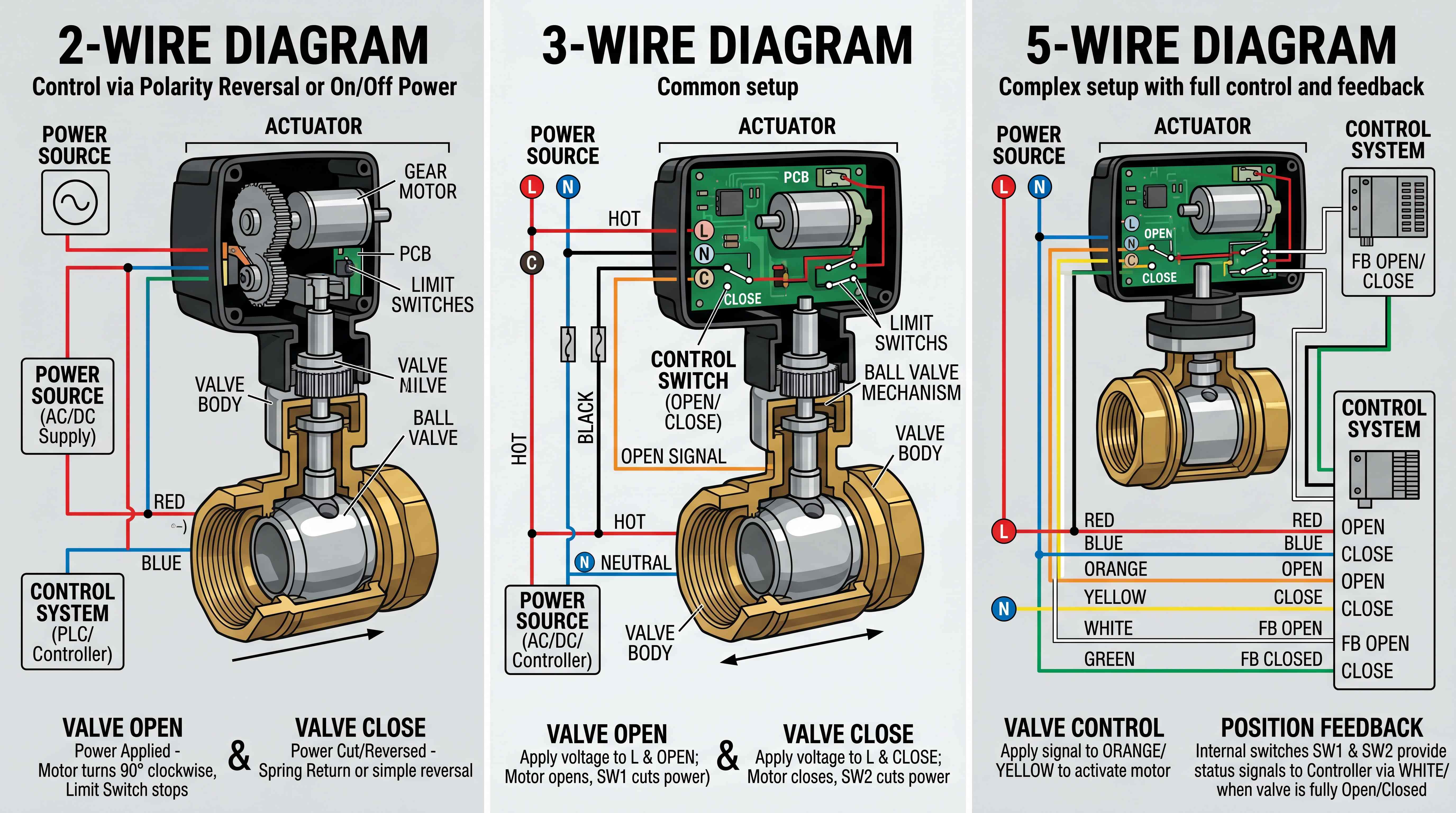
For on-off service, the actuator must open and close the valve reliably. It may include limit switches that stop the motor at the end of travel. It may also include manual override, position indicator and feedback contacts.
For modulating service, the actuator must do more than move between two positions. It must hold intermediate positions and respond to control signals. In this case, torque is still important, but positioning accuracy, control input, feedback and duty cycle become equally important.
Electric actuators should not be selected only from a torque number printed in a catalog. The engineer should also check voltage, enclosure rating, duty cycle, speed, manual override, feedback signal, ambient temperature, explosion-proof requirements and fail-safe behavior.
If the actuator is installed outdoors, moisture protection and cable sealing matter. If the valve is installed in a chemical area, corrosion protection matters. If the valve is used in a safety-related application, fail close or fail open behavior may require capacitor return, battery backup or another fail-safe design.
The right electric actuator is the one that provides enough torque and matches the control environment.
Pneumatic Actuator Torque Selection

Pneumatic actuator torque selection depends on valve torque and available air pressure. A pneumatic actuator converts compressed air pressure into rotary torque. If the air pressure is lower than expected, the actuator output torque will also be lower.
This makes site air pressure critical. A plant may have a compressor rated at a certain pressure, but the actual pressure at the actuator may be lower because of distance, pressure drop, regulator setting, small tubing or simultaneous air demand from other equipment. Actuator sizing should use the minimum reliable air pressure at the valve, not the ideal compressor pressure.
There are two common pneumatic actuator types: double acting actuator and spring return actuator. A double acting actuator uses air to open and air to close. A spring return actuator uses air in one direction and springs in the other direction.
Spring return actuators require careful sizing because spring torque changes through the stroke. The actuator must provide enough torque during both air-driven movement and spring-return movement. If the valve must fail closed, the spring must be strong enough to close the valve under process conditions.
Pneumatic actuator output can also vary depending on rack-and-pinion or scotch-yoke design. Torque may not be constant through the rotation. Engineers should check the torque curve, not only one maximum torque value.
Accessories also matter. Solenoid valve flow capacity, tubing size, air filter regulator, exhaust restriction and position feedback devices can affect operation. A correctly sized actuator can still perform poorly if the air control system is poorly designed.
A pneumatic actuator should be sized as part of a complete air-operated valve package.
ISO 5211 Actuator Mounting and Mechanical Fit
Torque is essential, but mechanical mounting is also critical. Many quarter-turn valves use ISO 5211 mounting patterns to connect actuators to valves. An ISO 5211 actuator interface helps standardize the flange pattern between the valve and actuator.
However, ISO 5211 compatibility does not automatically mean the assembly is correct. The mounting flange, stem size, stem shape, coupling, bracket height, bolt pattern and actuator rotation must all match.
For example, a valve and actuator may share the same ISO mounting pattern, but the stem may require a special coupling. If the coupling is loose, misaligned or incorrectly machined, the actuator may apply uneven force. This can damage the stem or create lost motion. If the bracket is weak or poorly aligned, the actuator torque may not transfer cleanly to the valve.
Mounting misalignment can increase operating torque. A valve that should require moderate torque may become difficult to turn because the actuator is not aligned with the stem. This can overload the actuator and shorten valve life.
For automated ball valves, the mechanical connection should be treated as part of the sizing decision. The actuator must not only produce enough torque; it must deliver that torque through a reliable mounting arrangement.
A good ISO 5211 actuator setup should provide stable alignment, correct coupling engagement, proper rotation angle and safe torque transfer. In industrial applications, this can be the difference between a reliable automated valve and a repeated maintenance problem.
Manual Override and Emergency Operation
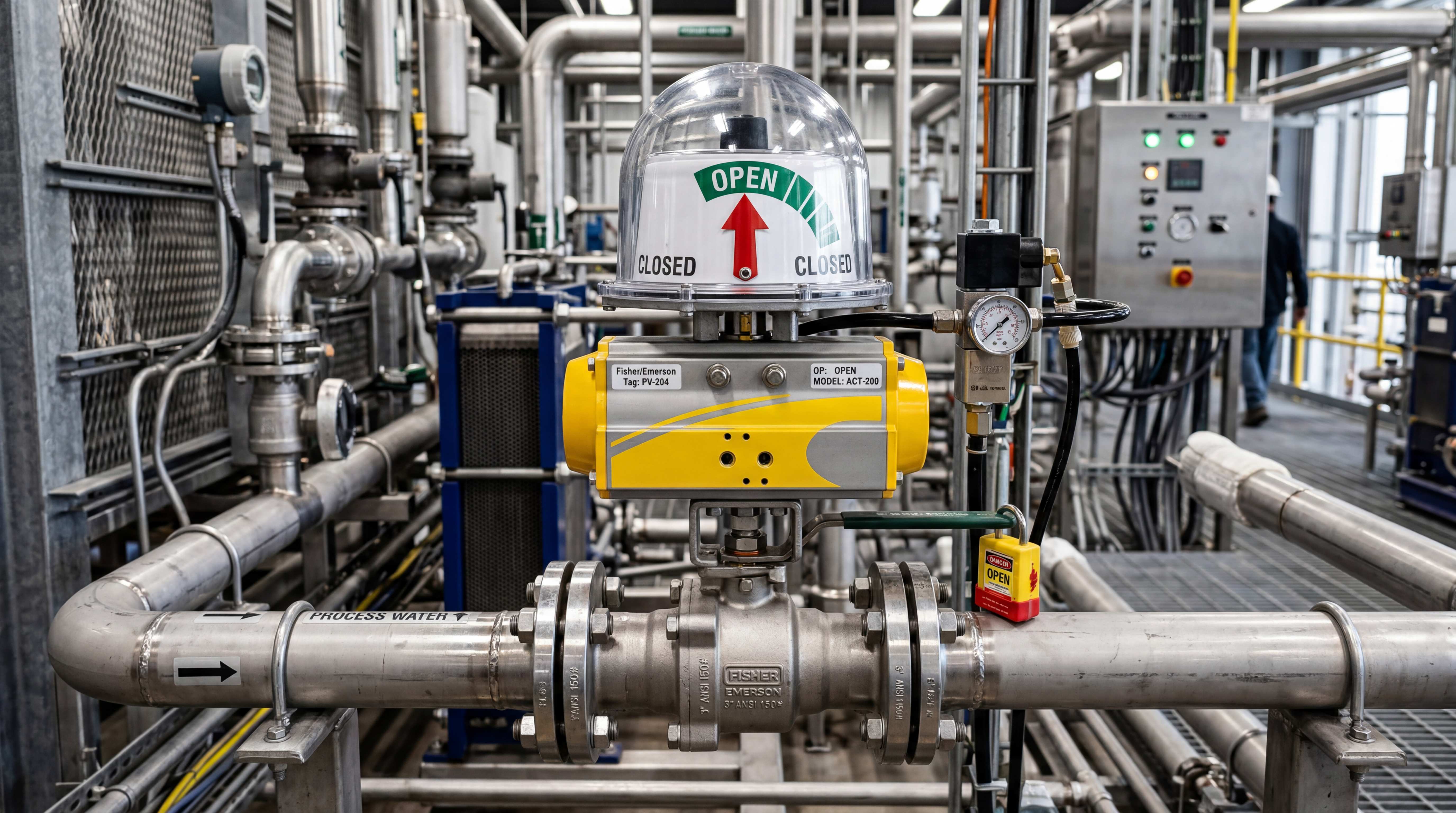
Manual override is often overlooked during actuator sizing, but it can be important in maintenance and emergency situations. A manual override allows operators to move the valve if the actuator power, air supply or control system fails.
In electric actuators, manual override may be a handwheel, lever or hex drive. In pneumatic actuators, manual override may be part of the actuator or added through a declutchable gearbox.
Manual override should be considered together with torque. If a valve requires high torque, the manual override must be practical and safe. A tiny manual mechanism may not be useful on a large or high-pressure valve. Operators should not need excessive force to move the valve during an emergency.
For spring return pneumatic actuators, manual override must be used carefully because the spring stores energy. The override design should match the safety requirements of the site.
Manual operation also helps during commissioning. Technicians may need to verify valve movement before connecting power or air. If the valve is difficult to operate manually, that may indicate torque issues, misalignment, debris or incorrect installation.
A reliable automated valve system should include a plan for what happens when automation is unavailable.
Position Feedback and Proof of Movement
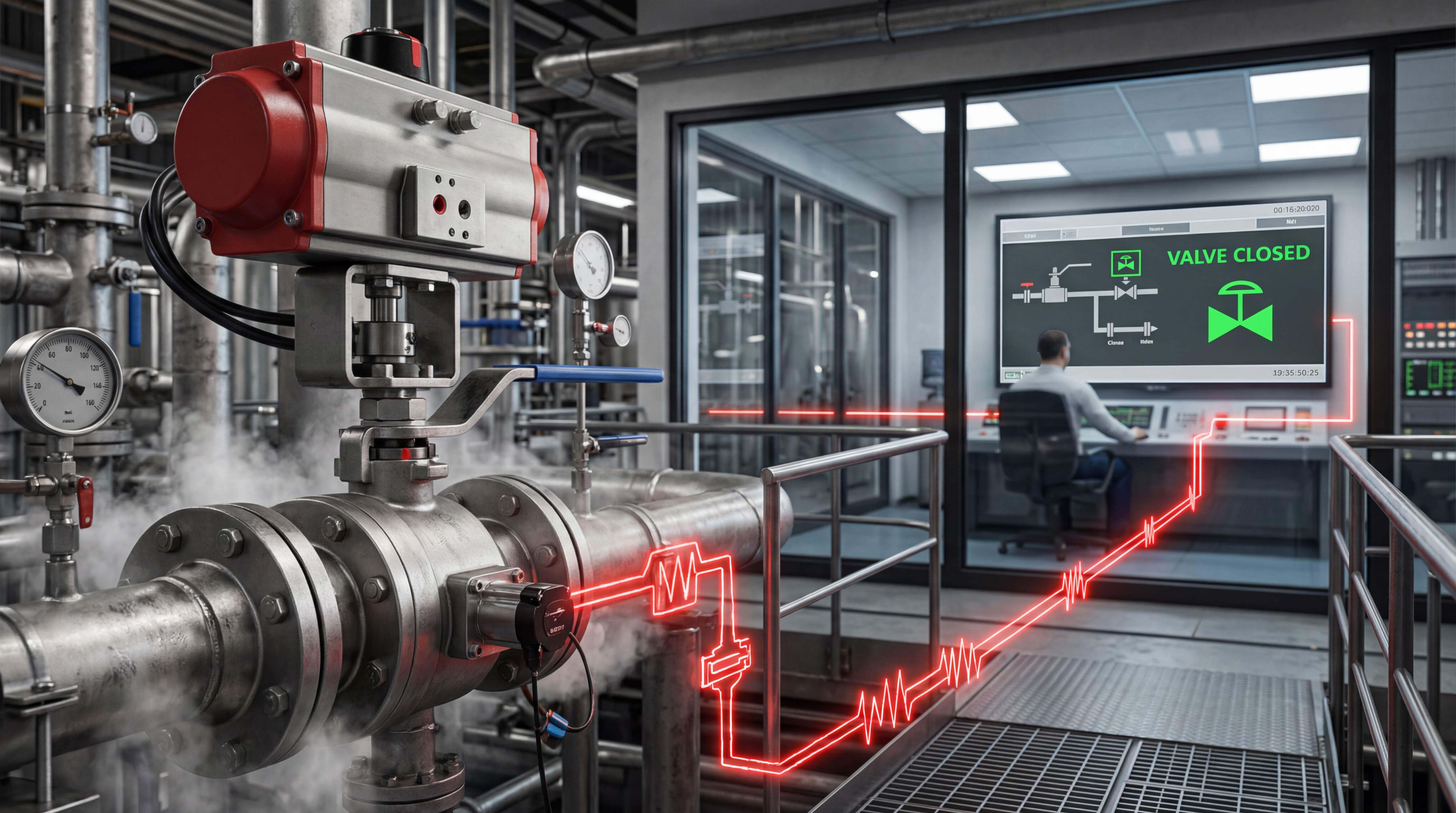
Actuator sizing is about making the valve move, but automation also needs proof that the valve moved correctly. Position feedback helps the control system confirm whether the valve is open, closed or in the commanded position.
For simple on-off ball valves, limit switches may confirm open and closed positions. For modulating valves, a position transmitter may provide continuous feedback. Some smart actuators can also report alarms, travel time, torque trends or fault conditions.
Feedback is especially important when actuator torque is close to the required limit. If the valve starts to stick or the actuator stalls, feedback can show that the commanded position was not reached. Without feedback, the control system may assume the valve is open or closed when it is not.
For example, if a pump starts while a valve remains closed, pressure may rise unexpectedly. If a chemical valve fails to close, dosing may continue. If a bypass valve fails to move, the process may not switch correctly. Position feedback reduces uncertainty.
Feedback does not replace proper actuator sizing, but it helps identify problems before they become hidden failures. In high-value process systems, actuator sizing and feedback should be considered together.
Common Actuator Sizing Mistakes

One of the most common mistakes is selecting the actuator based only on valve size. Pipe size does not define torque by itself.
Another mistake is using torque data without checking the service condition. A catalog value may apply to clean water, standard seats and moderate pressure. A chemical, slurry or high-pressure application may need more margin.
A third mistake is ignoring breakaway torque. Many valves fail to move because the actuator cannot overcome the first movement.
A fourth mistake is sizing pneumatic actuators based on ideal air pressure instead of minimum site air pressure. If the plant air system drops below the expected value, the actuator may fail.
A fifth mistake is oversizing without considering valve protection. Too much torque can damage the stem, seats or coupling if torque limits are not managed.
A sixth mistake is ignoring actuator duty cycle. An actuator may have enough torque but still fail if it cycles more frequently than its rating allows.
A seventh mistake is assuming ISO 5211 mounting means complete compatibility. The stem, coupling and bracket must also match.
An eighth mistake is ignoring aging. New valves usually operate more easily than valves after long service.
These mistakes can be avoided by treating actuator sizing as an engineering decision rather than a catalog shortcut.
A Practical Actuator Sizing Method
Start with the valve manufacturer’s torque data. Identify the required breakaway torque, running torque and seating torque if available. If only one value is provided, confirm what it represents.
Then define the service condition. Record media, pressure, temperature, valve material, seat material, operating frequency and installation environment.
Next, apply an actuator safety factor. The safety factor should reflect service severity. Clean water service may need less margin than sticky chemical, slurry, high-pressure gas or rarely operated emergency valves.
After that, choose the actuator type. Use an electric actuator if electrical control is preferred and the duty cycle, speed and environment are suitable. Use a pneumatic actuator if compressed air is available and the application needs fast movement, high cycling or spring return fail-safe behavior.
Then check available energy. For electric actuators, confirm voltage and power supply. For pneumatic actuators, confirm minimum air pressure at the valve location.
Next, verify mounting. Check ISO 5211 actuator flange, stem connection, coupling, bracket, rotation angle and mechanical alignment.
Then check control requirements. Does the valve need open-close control, modulating control, position feedback, manual override or fail-safe movement?
Finally, review long-term risk. Consider corrosion, deposits, maintenance access, spare parts and failure consequences.
This method helps ensure that quarter turn actuator sizing supports real field operation, not only theoretical installation.
Final Thoughts
Ball valve actuator sizing is not a small detail in valve automation. It is the engineering step that determines whether the automated valve will operate reliably in the real system.
The actuator must overcome ball valve torque, especially breakaway torque. It must handle valve pressure torque, media effects, seat friction, temperature changes, duty cycle and aging. It must also fit the valve mechanically through a correct ISO 5211 actuator mounting arrangement, coupling and bracket.
The best actuator is not always the largest actuator. It is the actuator with enough torque, proper safety factor, suitable duty rating, correct mounting, reliable control interface and appropriate environmental protection.
A properly sized actuator makes the valve predictable. An undersized actuator creates failure risk. An incorrectly mounted actuator creates mechanical stress. An oversized actuator without control can damage the valve. A poorly selected actuator may work during commissioning but fail after real service begins.
For engineers, buyers and system integrators, the practical rule is clear: do not size the actuator from valve size alone. Size it from torque, pressure, media, safety factor and real operating conditions. That is how an ordinary ball valve becomes a dependable automated flow control device.
Focused FAQ
What is ball valve actuator sizing?
Ball valve actuator sizing is the process of selecting an actuator with enough torque and suitable operating features to open, close or position a ball valve under real service conditions. It considers valve torque, pressure, media, safety factor, duty cycle and mounting compatibility.
What is ball valve torque?
Ball valve torque is the rotational force required to turn the valve stem and move the ball. It is affected by valve size, pressure, seat material, media, temperature, packing friction and valve condition.
What is breakaway torque?
Breakaway torque is the torque required to start moving the valve from a stationary open or closed position. It is often the highest torque point and is critical for actuator sizing.
Why is valve size alone not enough for actuator selection?
Valve size does not account for pressure, media, seat material, valve design, temperature, duty cycle or aging. Two valves of the same size may require very different actuator torque.
What is actuator safety factor?
Actuator safety factor is the extra torque margin added above the valve’s required torque. It helps the actuator operate reliably despite pressure changes, deposits, aging, seat friction and other real-world conditions.
How does pressure affect ball valve actuator sizing?
Higher process pressure can increase the force between the ball and seats, raising the torque needed to operate the valve. Pneumatic actuator output also depends on available air pressure.
What is an ISO 5211 actuator?
An ISO 5211 actuator is designed around a standardized mounting interface for quarter-turn valves. However, stem size, coupling, bracket alignment and torque compatibility must still be checked.
Can an actuator be too large for a ball valve?
Yes. An oversized actuator may increase cost and can damage the valve stem, seats or coupling if torque is not controlled properly. The actuator should provide enough margin without excessive force.
Why do automated ball valves fail to open?
Common causes include undersized actuator torque, low air pressure, wrong voltage, high breakaway torque, media deposits, corrosion, seat swelling, poor mounting alignment or incorrect control wiring.
What information is needed for actuator torque selection?
You need valve torque data, valve size, pressure, temperature, media, seat material, operating frequency, required safety factor, actuator type, air pressure or voltage, mounting interface and fail-safe requirements.
#BallValveActuatorSizing #BallValveTorque #BreakawayTorque #ValveTorqueCalculation #ActuatorTorqueSelection #QuarterTurnActuatorSizing #BallValveStartTorque #ValvePressureTorque #ActuatorSafetyFactor #ISO5211Actuator #BallValveAutomation #ValveAutomation #IndustrialComponents #FlowControl #ProcessAutomation