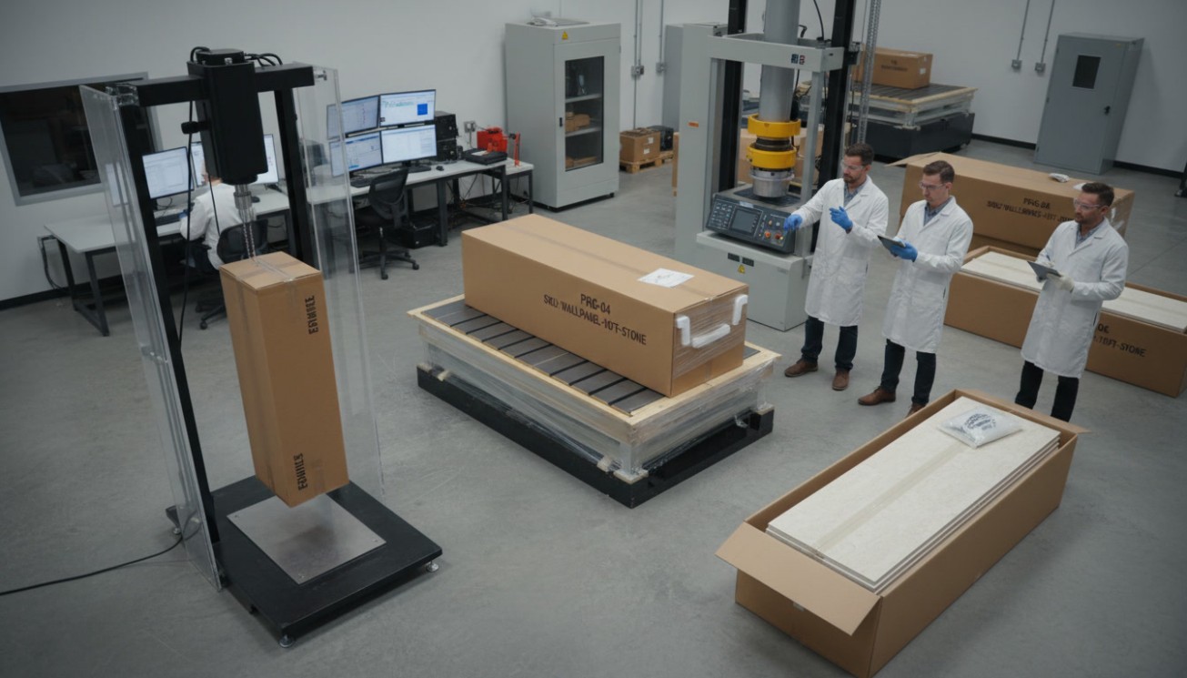
PU Wall Panel Adhesive and Substrate Compatibility Guide
Direct answer: There is no universal PU wall panel adhesive for every panel and wall. A reliable bond depends on the panel’s actual reverse face, the strength and condition of the substrate, adhesive chemistry, bead geometry, open time, cure environment, service exposure, movement and any mechanical restraint. Written manufacturer approval is the starting point, not proof of the installed assembly. Before full installation, test the production panel, specified adhesive and prepared project substrate together; agree acceptance criteria in advance; and record whether fracture occurs in the adhesive, panel, coating, paint film or wall. A strong initial grab is not a durability result.
Most installation pages answer a procedural question: measure, lay out, cut, apply, align and finish. This guide addresses the decision that comes before those steps: whether a particular bonding system is technically defensible for a particular wall. Readers who need the broader sequence should use our full installation sequence for PU stone panels. Here, the subject is compatibility, evidence and release.
The buying decision is a chain of interfaces, not a tube of glue
The common search for the best adhesive for PU wall panels assumes that the adhesive is the only variable. It is not. A bonded wall is a chain: panel core to molded skin, skin to overspray or backing treatment, backing to adhesive, adhesive to primer or paint, paint to substrate, and substrate to the wall structure. The assembly is only as reliable as its weakest link.
This explains a frequent complaint: the cured adhesive still feels hard and “strong,” yet a panel detaches. The glue may have remained intact while paint peeled from gypsum board, dust separated from concrete, a thin molded skin tore from the foam, or a coating released from the back of the panel. Calling every event an adhesive problem hides the corrective action. A failure investigation must identify the exact fracture plane.
Six variable groups should therefore be frozen before approval:
- Panel identity: model, mold, dimensions, lot, reverse-face material, skin, coating overspray and any factory treatment.
- Substrate identity: material, coating, age, condition, flatness, strength, moisture state and contaminants.
- Bonding products: adhesive, primer, cleaner and accessory products, including lot numbers and shelf-life status.
- Application process: preparation, bead or spread geometry, coverage, open time, pressure and temporary support.
- Cure conditions: temperature, relative humidity, ventilation, substrate moisture and time before loading.
- Service conditions: indoor or exterior exposure, heat, wetting, cleaning chemicals, impact, thermal cycling and movement.
If any one of these changes after the mockup, the evidence may no longer represent production work. That is why professional specifications approve a system and a process, not merely a brand name.
Map the bonded interface before selecting chemistry

The visible face of a faux-stone panel tells an installer almost nothing about the surface that must be bonded. Turn over panels from several cartons and inspect them under raking light. Look for glossy mold-transfer areas, powder, sanding dust, paint mist, release residue, voids, ribs, local high points and variation between molds or batches. Photograph representative backs beside their product and lot labels.
A rough-looking surface is not automatically bond-ready. Texture can increase effective area, but only if the adhesive wets the texture and the texture belongs to a sound layer. Dusty roughness creates a weak boundary. Conversely, a smooth skin is not automatically unacceptable; it may work with an approved chemistry and preparation. The conclusion must come from product documentation and representative tests.
Do not improvise aggressive abrasion, flame treatment, solvent wiping or primer use. Sanding can remove a load-bearing skin and expose weaker cells. A solvent can soften the polymer, redistribute release residue or react with back-coating. A cleaner that evaporates visually may still leave a film. Ask the panel and adhesive suppliers to approve the exact preparation, then include it in the test specimen and site method.
Room side → PU core → molded reverse skin or backing treatment → adhesive layer → approved primer or existing coating → substrate face → wall structure
Inspection question at every arrow: Is this interface chemically compatible, clean, sufficiently strong, correctly prepared and able to tolerate the expected movement?
Define the area that really carries load
Deeply molded panels may touch a flat wall only at ribs or islands. Nominal panel area is therefore not bonded area. The team should document where adhesive can be placed without holding the panel away from its intended plane, how compression changes bead thickness, and whether voids create peel leverage at edges. A drawing of the reverse face with approved bonding zones is more useful than a vague instruction to “apply enough adhesive.”
Separate supplier approval from project validation
A supplier statement such as “suitable for polyurethane” addresses only part of the system. Ask whether approval covers the exact foam formulation, molded skin, paint overspray, cleaning method, substrate and exposure. Then validate the delivered combination. This two-step discipline is the practical meaning of wall panel substrate compatibility: documented plausibility followed by evidence from the real assembly.
Diagnose the wall before it becomes a specimen
The wall is not simply “drywall” or “concrete.” Its outermost load-carrying layer may be old paint, skim coat, curing compound, laitance, sealer, tile glaze, oxidation, wallpaper residue or construction dust. The adhesive bonds to what it touches, while gravity and movement eventually ask that surface to transfer load deeper into the assembly.
A practical substrate survey combines visual inspection, hand tools, documented moisture or condition checks appropriate to the material, and small destructive probes where permitted. The goal is not to generate a universal pass number. It is to identify weak boundary layers and select project criteria from the adhesive data sheet, substrate manufacturer, designer and applicable project documents.
| Substrate | Checks before selection | Preparation route to confirm | Representative validation | Stop condition |
|---|---|---|---|---|
| Painted gypsum board | Paint adhesion, chalking, soft paper, joint-compound condition, repairs, moisture staining and wallboard attachment | Retain, remove or prime the coating only under an approved method; repair unsound paper or compound | Test across field paint and a repaired joint because the weaker zone may control | Peeling paint, torn paper, soft board, active moisture or unknown incompatible coating |
| Bare gypsum board | Paper integrity, dust, damaged face, fastener support and differential suction at compounds | Use only an approved sealer or primer where required; do not saturate or polish the paper | Mock up both paper and joint-compound areas | Delaminated paper, friable compound or inadequate wallboard support |
| Concrete or masonry | Cure state, laitance, dust, curing compounds, sealers, contamination, moisture, alkalinity, cracks and flatness | Remove unsound boundary layers using a documented method; repair and prime only as specified | Use site coupons or an agreed pull-off approach at representative locations | Active water, condensation, friable surface, incompatible sealer or values outside product/project limits |
| Cement board | Board type, face treatment, dust, joints, framing support, fasteners and exposure rating | Follow board and adhesive requirements for cleaning, joint treatment and primer | Full assembly mockup spanning a board joint where relevant | Loose board, unsupported joints, surface dusting or incompatible factory treatment |
| Plywood or OSB | Grade, moisture, swelling, face treatment, resin-rich areas, orientation, fastener pattern and movement potential | Condition material and use only approved abrasion or primer procedures | Test representative face and edges after expected conditioning | Wet, warped or delaminated sheet; unsupported movement; unknown preservative or coating |
| Existing tile | Tile-to-wall bond, hollow areas, glaze, contaminants, grout condition, moisture path and flatness | Degrease and prepare glaze only by a system-approved method; remove loose tile | Mock up across tile and grout with the real cleaner/primer sequence | Hollow or loose tile, trapped moisture, incompatible cleaner, movement crack or failed waterproofing |
| Metal | Alloy, coating, oxidation, oil, condensation, thermal movement and galvanic/accessory concerns | Use the adhesive maker’s cleaning and primer schedule for that metal/coating | Conditioned coupon plus assembly mockup where temperature cycling matters | Active corrosion, persistent condensation, unidentified finish or excessive movement |
Painted walls: test the paint, not just the glue
To install PU panels on drywall safely, confirm that the paper, joint compound, primer, paint and wallboard attachment form a stable chain. A high-strength adhesive can simply become an efficient paint-removal tool. Cross-cut or pull checks may help characterize a coating, but the designer or manufacturer must decide the appropriate method and acceptance. Where paint identity or age is unknown, a representative test area is essential.
Mineral walls: dry-looking is not the same as suitable
For PU wall panels on concrete, surface moisture, internal moisture movement, alkalinity, curing compounds and laitance can alter both adhesion and cure. No single moisture or pH limit applies to every adhesive. Record the instrument, method, locations, date and project threshold. If the wall is below grade or shows efflorescence, solve the moisture source before cladding it.
Tile overlays: the old installation becomes part of the warranty chain
Installing PU wall panels over tile may appear convenient, but it adds another interface. Tap or otherwise assess the tile field using an approved survey method, map cracks and hollow zones, and determine whether joints indicate movement. An adhesive that bonds brilliantly to glazed ceramic cannot compensate for tile that is weakly attached to its backing or for water moving through a failed wet-area assembly.
Choose a cure architecture, not a marketing adjective

“High grab,” “heavy duty,” “waterproof” and “multi-surface” are not complete selection criteria. Adhesive families differ in how they build strength, what they release, how they tolerate bond-line thickness and whether they need water, air, mixing or solvent escape. The product data sheet and safety data sheet must govern. The following categories are decision prompts, not universal recommendations.
Water-based products
Water-based construction adhesives may be convenient and lower in odor, but cure depends on water leaving the bond. Two low-permeability surfaces or a thick, continuous bed can slow that path dramatically. A product that cures quickly between porous laboratory materials may remain soft behind a coated panel on glazed tile. Confirm at least one surface can support the specified drying mechanism, and evaluate the actual thickness and temperature.
Moisture-curing products
Moisture-curing chemistries use available moisture to react, but “more moisture” is not automatically better. Low temperature or humidity can slow cure; a sealed interface can limit exposure; excessive water can cause other defects depending on chemistry. As one product-specific example, Sika’s May 2026 data sheet for a polyurethane construction adhesive states that its system is moisture-cured, requires sufficient air exposure, slows under low temperature and humidity, and has explicit substrate limitations. Those statements illustrate why the current data sheet matters; they do not make that product a default recommendation for PU panels.
Two-component reactive products
Two-component systems do not rely on evaporation in the same way, but they introduce ratio, mixing, induction, pot-life and application-control risks. A high laboratory value is irrelevant if site crews use partly mixed material, apply after pot life, or change bead thickness. Packaging format, dispensing equipment, worker training and waste control become part of compatibility.
Solvent-containing products
Solvent can help application and early grab, yet it may attack foam, soften a coating, stress-crack a polymer or become trapped between impermeable surfaces. “Safe for polyurethane” should be confirmed against the exact panel construction. A short spot check can screen obvious damage, but some softening, discoloration or embrittlement may require longer observation and conditioned tests.
| Variable | Why it matters | Evidence to request or record |
|---|---|---|
| Approved adherends | “Wall panel” does not identify PU skin, paint, tile glaze or coating chemistry | Written compatibility for both delivered panel back and prepared substrate |
| Cure mechanism | Water, air, humidity, temperature, mix ratio and bond thickness affect strength development | Current product data sheet, cure curve or technical-service confirmation for project conditions |
| Initial grab versus final properties | A panel can resist sliding while the internal bond is still immature | Fixture requirement, handling time and full evaluation time stated separately |
| Open time and skin formation | Late placement can transfer a skinned bead without wetting the second surface | Maximum allowed interval and a site method for timing each panel |
| Bond-line thickness | Too thin can starve uneven areas; too thick may cure slowly or increase creep | Approved nozzle, bead geometry, compression method and inspected mockup sections |
| Movement capability | Peak strength alone does not show ability to accommodate differential movement | Relevant flexibility, modulus, creep or cycling data tied to assembly design |
| Temperature and wet exposure | Heat, water and cycling can change the adhesive or adjacent layers | Conditioned results matching intended service, plus documented limitations |
| Primer and cleaner | An accessory can improve one interface while damaging another | Exact product, batch, application rate, drying window and compatibility approval |
| VOC, fire and occupational controls | Installation chemistry may affect indoor-air requirements, worker safety and project approvals | SDS, regulatory documentation, ventilation plan and project review |
| Shelf life and storage | A correct product can behave incorrectly after heat exposure, freezing or expiration | Lot, expiry, storage log and incoming condition |
Engineer bead geometry and working time
Application geometry controls how load, air and moisture move through the bond. Dots can concentrate stress and allow local rocking. Parallel beads may create drainage or ventilation paths, but their direction also matters. A perimeter bead can trap air or moisture. Full-spread application maximizes nominal contact but may create a sealed interface and makes thickness control critical. None is universally correct.
The method statement should state nozzle cut, bead width and height, bead location, spacing pattern, adhesive quantity per panel, placement pressure, final stand-off, maximum open time, repositioning rule and support period. Use a consumption check: weigh cartridges or count panels per cartridge, and compare actual use with the approved mockup. Consumption is not proof of contact, but a large deviation exposes process drift.
Open time begins when the adhesive is exposed, not when the installer remembers to check the clock. On a large relief panel, application itself may consume much of the workable interval. Wind, heat and absorbent surfaces can change skin formation. A useful site control is to mark each panel with application and placement times and periodically lift a sacrificial panel during trial work to examine transfer. The approved PU wall panel installation adhesive process must define what adequate transfer looks like.
Initial grab is a positioning property
Installers often judge a product by whether the panel slides. That property affects productivity, but it is not the same as cured load capacity or ageing resistance. Temporary bracing, pins, battens or tape may hold alignment while the chemical bond develops. Their removal time must follow the documented cure condition, not a generic “next day” habit.
Movement changes the question from strength to stress management
A rigid coupon test commonly loads a small, well-aligned joint once. A wall experiences panel bow, substrate movement, thermal cycles, building drift, localized impact and peel forces at edges. High lap-shear performance does not necessarily mean high resistance to cyclic peel, creep or a moving substrate.
Exterior and sunlit walls deserve particular scrutiny. Dark textures can heat unevenly; long elevations accumulate dimensional change; joints and openings interrupt restraint; and water may reach edges or the back. Our guide to exterior drainage and substrate design covers the wider exposure decision. For the bond specification, translate that environment into test conditioning, movement review, edge details and fastening requirements.
Do not ask the adhesive to solve movement that the wall design should accommodate. Review panel dimensions, expected temperature range, substrate type, joint layout, edge clearances, openings, transitions and sealant interfaces. Adhesive flexibility, joint design and mechanical restraint need to be considered together. A very stiff bond can shift stress into foam skin, paint or paper; a compliant bond can reduce stress concentration but must still control long-term creep.
Use mechanical restraint as a defined load path
Mechanical fasteners for wall panels should not be added as unexplained insurance. A screw only works if it engages a suitable substrate, has an approved head or washer geometry, is placed in a panel zone capable of transferring load, and is detailed against pull-through, corrosion, water entry and visible damage.
Distinguish three functions:
- Temporary restraint prevents slide, spring-back or loss of contact while the adhesive cures.
- Permanent redundancy provides a second attachment path if a bonded interface deteriorates.
- Primary mechanical attachment carries defined service loads while adhesive may distribute load, damp vibration or control local contact.
Permanent restraint is more likely to require design review at high elevations, above occupied paths, around openings, on exterior walls, on unstable coatings, or where consequence of detachment is high. It can also be required by the panel manufacturer, adhesive manufacturer, designer, code or warranty. This guide intentionally gives no universal spacing: spacing depends on panel strength, fastener capacity, support layout, wind or impact demand, edge distances and project approval.
Build evidence in five gates

A defensible validation program moves from inexpensive screening to representative installation. Each gate answers a different question; passing an early gate does not waive the later one.
Gate 1: document and surface screen
Review panel and adhesive documents, identify restrictions, inspect the reverse face and substrate, and perform small compatibility observations. ASTM D3808 describes a qualitative spot-adhesion method for quickly screening whether an adhesive bonds to a substrate and for comparing candidates. It is useful as a screen, not a quantitative wall acceptance test.
Gate 2: controlled comparative coupons
Use repeatable coupons to compare preparation routes, adhesive candidates or conditioning. Record specimen geometry, overlap or bonded area, bond thickness, preparation, cure and loading rate. ISO 4587 specifies tensile lap-shear testing of rigid-to-rigid bonded standard specimens under defined preparation and test conditions—and explicitly says the procedure does not provide design information. Results can rank controlled combinations; they cannot be pasted into a wall calculation as guaranteed capacity.
Gate 3: representative assembly mockup
A PU wall panel field mockup should use production panels, production substrate or an accepted representative, actual coatings, specified preparation, planned bead geometry, site tools, trained installers, temporary support and expected environmental conditions. Include joints, corners or openings if they create the highest risk. Make the mockup large enough to reveal panel bow and working-time issues that small coupons cannot show.
Gate 4: agreed field evaluation
A wall panel adhesion test must have a written purpose. Is it screening surface suitability, comparing preparations, measuring substrate tensile strength, checking transfer, or verifying a minimum project criterion? The fixture adhesive, dolly size, cut around the test area, loading device and failure plane can all affect a pull result. ASTM C1583/C1583M is relevant to direct-tension pull-off evaluation of concrete surfaces and repair/overlay bonds; its scope reinforces the need to identify whether failure occurred in the substrate, overlay or bond. Project professionals must adapt or select an appropriate method rather than casually claiming compliance.
Gate 5: production release and surveillance
Release only after the responsible parties sign the substrate condition, approved products, mockup outcome and environmental limits. Then monitor production: first-off panel, periodic adhesive consumption, open-time records, ambient conditions, lot changes and observed transfer. Testing one perfect area does not control hundreds of uncontrolled panels.
Set acceptance criteria before the result exists
Acceptance should address measured force where appropriate, failure mode, bonded transfer area, panel position after cure, appearance and absence of damaging chemical interaction. Criteria created after a disappointing result are negotiation, not quality control. If multiple failure modes occur, report them separately rather than averaging unlike outcomes.
Read the fracture surface like a diagnostic record
The location of fracture answers “what was weakest under this test?” It does not automatically answer “what will fail first after ten years?” Still, it is far more informative than peak force alone. ISO 10365:2022 provides designations for main failure patterns of bonded assemblies across mechanical tests. A project can use an adapted, clearly defined code set for consistent field reporting.
AF-P: clean separation at panel/adhesive interface → investigate panel skin, contamination, preparation and wetting.
CF-A: fracture through adhesive body → investigate cure, thickness, ageing and whether the cohesive result meets the agreed criterion.
CF-P: foam or panel-skin tear → the panel layer controlled this test; examine depth, variability and consequence.
DF-C/S: paint, skim coat or substrate delamination → the wall-side layer controlled; stronger glue alone is not the remedy.
MF: mixed fracture → estimate and photograph percentages by region; do not erase the weak interface by calling everything “mixed.”
A credible PU panel adhesive failure report includes both faces of the fracture, a scale, orientation, specimen ID, environmental history and an annotated percentage map. Photograph immediately; dust or handling can obscure the surface. Preserve samples if supplier analysis may be needed.
Why equal peak values can lead to different decisions
Imagine two tests with similar peak force. In one, the adhesive fractures cohesively after uniform transfer. In the other, half the paint film peels cleanly from the wall. The numerical result may look similar, but the second points to a variable substrate layer and possibly wider field risk. Conversely, substrate fracture is not automatically a perfect pass: it may reveal that the substrate itself is unacceptably weak or that the test damaged only a shallow local zone.
Age the assembly for the service it will actually see
Short-term room-temperature adhesion answers a narrow question. It does not establish resistance to heat, humidity, water, cleaning agents, freeze-thaw cycling, UV at exposed edges or repeated movement. Select preconditioning from the project’s exposure map and the claims being made.
- Dry interior: normal occupancy temperature, expected cleaning and realistic cure before loading.
- Humid interior: elevated humidity, condensation risk and wet-cleaning exposure where relevant.
- Exterior sheltered: thermal cycling, intermittent wetting, cold conditions and edge exposure.
- Exterior exposed: project climate, solar heating, wet-dry or freeze-thaw cycles, drainage details and wind-related movement.
- Special use: chemical cleaning, heat source, splash, high impact or other documented stressors.
Conditioned specimens need controls from the same batch tested without conditioning. Otherwise, the team cannot separate ageing effects from ordinary specimen variability. Record appearance, mass or dimensions if relevant, maximum force, displacement behavior and failure mode after exposure. Do not claim service life by simply multiplying a laboratory duration.
Turn the mockup into a release record
A field trial is valuable only if somebody can reconstruct it. Use a controlled form rather than a photo labeled “test passed.” The record below can become the core of an Adhesive Compatibility & Field Mockup Record.
| Record field | Required entry | Why it matters |
|---|---|---|
| Assembly ID | Project, room/elevation, wall grid, panel model/lot and substrate zone | Connects evidence to the installed population |
| Wall condition | Material, coating, age, repairs, flatness, moisture/condition method and result | Prevents “same wall” assumptions |
| Panel back | Photographs, skin/overspray observations, cleaning or preparation | Defines the first adherend |
| Products | Adhesive, primer, cleaner, lots, expiry and storage condition | Controls chemistry and traceability |
| Application | Nozzle, bead map, quantity, application time, placement time, pressure and support | Reproduces bond-line formation |
| Cure history | Date/time, temperature, relative humidity, ventilation, disturbance and elapsed cure | Separates product selection from incomplete cure |
| Test method | Purpose, geometry, device ID/calibration, rate, cut/no-cut detail and locations | Makes numerical results interpretable |
| Result | Peak force/stress where valid, transfer area, displacement and visual condition | Captures performance beyond one number |
| Failure code | AF-P, AF-S, CF-A, CF-P, CF-S, DF-C/S or MF, with estimated percentages | Identifies the weak link |
| Disposition | Accept, reject, revise preparation, change product, add restraint or retest | Turns observation into controlled action |
| Authorization | Installer, contractor QC, manufacturer/technical representative and designer as required | Establishes responsibility for release |
Hold points that prevent a small uncertainty becoming a full-wall defect

Hold points are planned pauses requiring evidence and authorization. They protect schedule because uncertainty is cheapest before hundreds of panels are installed.
Pre-installation hold point
Confirm approved submittals, delivered product identities, trained installers, substrate survey, mockup acceptance, environmental limits and support/fastener plan. If the product or wall differs from the mockup, do not quietly proceed.
First-off hold point
Inspect the first installed panel or small area for adhesive transfer, final plane, squeeze-out, working time and temporary restraint. A reversible first-off check can expose incorrect nozzle cuts, skinned beads and unanticipated high spots.
Production surveillance
Record conditions at defined intervals and after breaks, weather changes or crew changes. Check consumption and open-time compliance. Map areas completed with each adhesive lot. If a carton lot has a visibly different back surface, treat it as a material change.
Stop-work triggers
- Loose paint, paper tear, dusting, crumbling or unexpected substrate fracture.
- Active leak, dampness, condensation, efflorescence or a documented condition outside project/product limits.
- Panel-back contamination, softening, swelling, discoloration or batch-to-batch surface change.
- Expired, frozen, overheated, poorly mixed or unidentified bonding product.
- Exceeded open time, inadequate transfer, abnormal cure or loss of temporary support.
- Mockup/test result below the pre-agreed criterion or a new failure mode.
- Unapproved change in substrate, adhesive, primer, cleaner, panel lot, installer or exposure.
After a trigger, isolate the affected area, record the last known conforming point, determine cause, approve corrective action and repeat appropriate validation. Covering the evidence with the next panel is not a corrective action.
What a project submittal should contain

For a small residential feature wall, the record may be brief. For hotels, retail programs, high walls and multi-site rollouts, a formal package reduces disputes between procurement, design, distribution and installation. Our discussion of commercial project submittals and responsibility explains the wider program context.
The bonding submittal should identify:
- panel model, dimensions, mass, finish, back surface, manufacturing lot and intended application;
- substrate assembly from visible surface through structural support, including coatings and repair materials;
- adhesive, primer, cleaner and sealant product data sheets and safety data sheets;
- written compatibility statements and all stated exclusions;
- surface preparation, environmental limits, bead map, coverage, open time, pressure and support;
- joint, edge, opening, transition and movement details;
- temporary and permanent restraint design, including responsible approver;
- coupon/mockup methods, conditioning, acceptance criteria, results and fracture photographs;
- jobsite hold points, stop-work triggers, nonconformity process and change control;
- maintenance, inspection and replacement provisions.
Procurement must freeze the tested identities. Substituting an “equivalent” adhesive after award can alter solvent content, cure mechanism, flexibility, open time and substrate limitations. Similarly, changing panel finish or factory process can change the back. Any substitution needs technical review and proportionate revalidation.
Three decision scenarios
Scenario A: painted office feature wall
The wall is flat and dry, but the paint identity is unknown. The risk is not primarily panel weight; it is coating adhesion and variable joint-compound zones. The team maps repairs, tests the paint layer, prepares two representative trial areas and compares fracture surfaces after the specified cure. If paint releases, it revises the wall preparation instead of shopping for ever-stronger glue. Concealed temporary restraint controls alignment during cure.
Scenario B: tile renovation in a humid room
The tile is glossy and largely intact, but several hollow areas and a movement crack are found. The correct decision is not to apply more primer. The team first determines whether the existing tile and backing can remain and whether moisture management is functional. It removes or repairs unacceptable areas, then validates the approved cleaner, primer and adhesive across tile and grout. Wet-area suitability remains an assembly question, not an adhesion-only claim.
Scenario C: exterior commercial accent above a public path
Consequence of detachment is high, the substrate moves with temperature and the elevation receives rain. Adhesion-only release is insufficient. The designer coordinates drainage, joints and a corrosion-appropriate permanent attachment path; the team conditions mockups for relevant exposure; and acceptance includes failure pattern and panel behavior, not just a short-term pull value. Product, substrate and fastener responsibilities are explicit before procurement.
Focused FAQ
Can PU wall panels be glued directly to painted drywall?
Sometimes, but only when the panel and adhesive are approved for the coating and the paint, primer, joint compound, paper face and wallboard attachment are sound. Clean appearance is not proof of coating adhesion. Test representative field paint and repaired or joint-compound areas using the specified preparation and full cure. If paint or paper releases, correct the substrate; a stronger adhesive does not repair a weak wall layer.
Can panels be installed over tile or concrete?
They may be, but the decision differs by substrate. Tile must be securely bonded, clean, compatible with the preparation and free of unresolved movement or moisture problems. Concrete must have sound near-surface material and be evaluated for relevant moisture, alkalinity, curing compounds, sealers and contamination. Validate the exact site assembly. Do not transfer an approval for clean laboratory ceramic or concrete to an unknown existing wall.
How long should a field adhesion test cure before evaluation?
Use the current adhesive data sheet and written technical guidance for the actual temperature, humidity, bond thickness, porosity and ventilation. “Grab time” and “full evaluation time” are different. Some cure mechanisms slow substantially in cold, dry or sealed conditions. Record the entire cure history, and do not shorten it simply to protect the schedule.
Does a higher lap-shear result mean a safer wall installation?
No. Lap shear can compare controlled rigid specimens, but a wall also experiences peel, bow, creep, cyclic movement and weak coating or substrate layers. ISO 4587 itself states that its procedure does not provide design information. Interpret the value with specimen geometry, conditioning and failure mode, then confirm the representative wall assembly.
When should screws be used with adhesive?
Use screws or another approved restraint when required by the panel system, adhesive instructions, designer, code, warranty or project risk assessment. Common reasons include temporary fixture, high consequence of detachment, exterior loads, edges/openings, overhead or high-level work and the need for permanent redundancy. The fastener must engage suitable support and transfer load without pulling through the panel. Spacing and type are project-specific.
What is the fastest useful preconstruction test?
A documented spot-adhesion screen can eliminate obviously incompatible combinations, and ASTM D3808 is one recognized qualitative framework. It cannot replace a representative mockup or agreed quantitative evaluation. The quickest responsible program is staged: screen early, compare controlled variants, then validate the final assembly before mobilizing a full crew.
Final specification rule: approve the weakest link you can observe
The professional question is not “Which glue is strongest?” It is “Which documented assembly remains acceptable after realistic preparation, cure, loading, movement and exposure—and where does it fracture when challenged?” That question turns adhesive selection from a purchasing shortcut into installation engineering.
Do not release this guidance as a project recommendation until the actual production panel, adhesive and at least two representative substrate conditions have been tested or supported by anonymized project evidence. Every recommendation should trace to current manufacturer documentation or project validation, and a qualified technical reviewer should confirm that comparative test data has not been presented as design capacity or a service-life guarantee.
Technical sources
- ISO 4587:2003 — tensile lap-shear strength of rigid-to-rigid bonded assemblies; the official scope states that the method does not provide design information.
- ISO 10365:2022 — designation of main failure patterns in bonded assemblies.
- ASTM D3808-01(2021) — qualitative spot-adhesion screening for adhesive/substrate combinations.
- ASTM D903-98(2025) — comparative peel or stripping strength under defined specimen and test conditions.
- ASTM C1583/C1583M-25 — direct-tension pull-off testing for concrete surfaces and repair/overlay bonds.
- SikaBond Construction Adhesive Product Data Sheet, May 2026 — a product-specific example showing how cure conditions, substrate restrictions and preparation requirements affect use.
- Sika: Proper Surface Preparation — manufacturer guidance emphasizing clean, sound and appropriately prepared surfaces.