2-Way vs 3-Way Ball Valve: L-Port, T-Port and Flow Direction Mistakes
Why Flow Direction Matters More Than Many Buyers Think
A ball valve may look simple from the outside, but the flow path inside the valve determines how the whole system behaves. This is especially true when comparing a 2 way ball valve and a 3 way ball valve. Many selection problems do not happen because the valve body is weak or the actuator is poor. They happen because the buyer misunderstands the internal ball valve flow pattern.
A 2 way ball valve is easy to understand. It has one inlet, one outlet and one straight-through path. When the bore inside the ball is aligned with the pipeline, the valve is open. When the ball turns 90 degrees, the valve is closed. This makes it ideal for basic on-off isolation.
A 3 way ball valve is different. It has three ports and an internal flow path that may be shaped like an L or a T. That design allows the valve to direct flow between different pipeline branches. It can act as a diverting ball valve, a mixing ball valve or a multiport ball valve depending on the internal ball design and the rotation position.
The challenge is that many users only look at the external valve shape. They see three connections and assume the valve can perform any three-way function. In reality, the flow path is determined by the drilled passage inside the ball. An L port ball valve and a T port ball valve may look similar from outside, but they can behave very differently in a real pipeline.
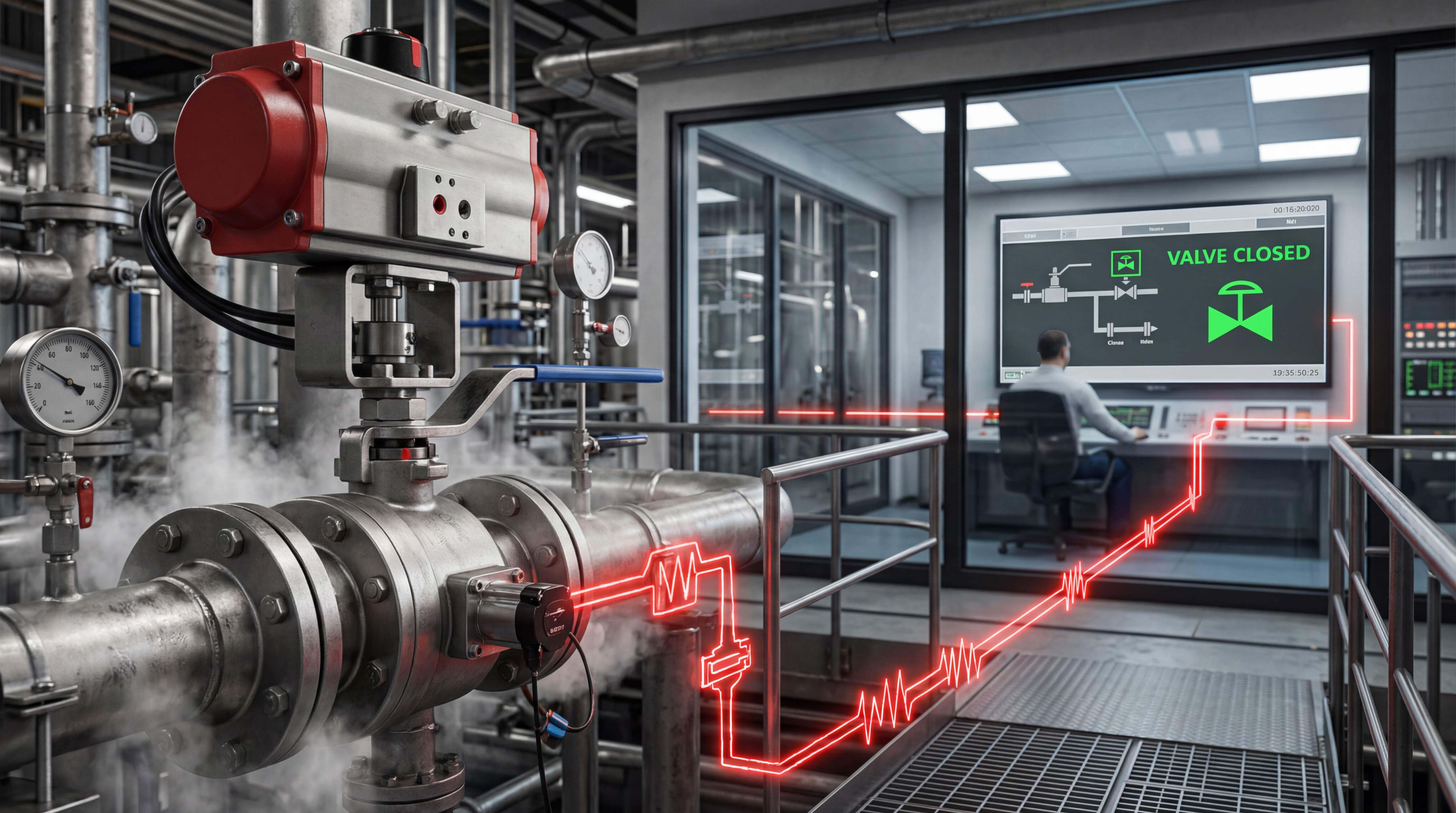
This becomes even more important in valve automation. Once a manual valve is fitted with an actuator, the valve does not rely on an operator visually checking the handle position. It follows a control signal. If the 3 way ball valve flow direction is misunderstood, the automated system may send flow to the wrong branch, block a necessary bypass, connect two lines unintentionally or fail to isolate the process safely.
For this reason, choosing between a 2-way and 3-way ball valve should not start with price or connection size. It should start with one question: what exactly must the flow do?
The Basic Role of a 2-Way Ball Valve
A 2 way ball valve is the standard ball valve most people know. It has two ports: one upstream and one downstream. Its function is usually to start or stop flow. In industrial systems, it is often used as an isolation valve, shut-off valve, drain valve, bypass valve or service valve.
The internal structure is straightforward. The ball has a hole through the center. When the hole aligns with the pipe, fluid passes through. When the ball rotates one quarter turn, the solid part of the ball blocks the flow path. Because the motion is only 90 degrees, this design is easy to automate with an electric actuator or pneumatic actuator.
A 2-way valve is often the best choice when the system only needs open-close control. For example, a water treatment skid may use a 2 way ball valve to open or close an inlet line. A chemical dosing system may use it to isolate a chemical feed path. An HVAC system may use it to shut off chilled water flow to a branch line. A compressed air system may use it as a service isolation valve.
The advantage of a 2 way ball valve is clarity. There are only two main states: open and closed. This makes operation simple, troubleshooting easier and control logic cleaner. In automated systems, a 2-way valve can be connected to a PLC, relay, timer or sensor with relatively straightforward logic. The controller sends an open command or a close command, and feedback switches can confirm the valve position.
However, a 2-way valve cannot change flow direction between multiple outlets. It cannot mix two inlet streams into one outlet. It cannot choose between two different supply lines by itself. If the system needs flow routing, not just isolation, a 3 way ball valve may be required.
What Makes a 3-Way Ball Valve Different
A 3 way ball valve has three pipeline connections instead of two. These connections are usually arranged in a T-shaped or L-shaped body configuration, depending on the design. The valve may have one common port and two branch ports, or it may connect different ports depending on ball position.
The key difference is not only the third port. The real difference is the internal ball valve flow pattern. The ball inside the valve is drilled to create an L-shaped passage or a T-shaped passage. That internal passage determines which ports are connected when the valve rotates.
A 3 way ball valve can perform functions that a 2-way valve cannot. It can divert flow from one inlet to one of two outlets. It can select between two inlet sources and send one of them to a common outlet. It can mix two streams into one outlet in some configurations. It can provide bypass control, drain routing or process switching.
This is why 3-way valves are common in water treatment, chemical processing, HVAC, thermal management, filtration systems, dosing systems, fluid transfer skids and OEM equipment. Wherever one pipeline needs to connect to different flow paths, a multiport ball valve may reduce the number of separate valves required.
But this flexibility creates selection risk. A 3-way valve is not automatically more capable than a 2-way valve. It is more application-specific. If the L-port or T-port design does not match the required flow logic, the valve may be physically installed correctly but functionally wrong.
In a manual system, an operator may sometimes compensate by learning the handle positions. In an automated system, there is less room for interpretation. An electric 3 way ball valve or pneumatic 3-way valve must rotate to exact positions that match the control program. If the flow path is wrong, the automation logic becomes wrong.
L-Port Ball Valve: Best for Diverting and Source Selection

An L port ball valve has an internal passage shaped like the letter L. This means the ball usually connects the common port to one of two side ports at a time. It is commonly used when the system needs to choose one flow path and block the other.
The most common use is diverting. In a diverting ball valve arrangement, one inlet enters the common port, and the valve sends flow to either outlet A or outlet B. For example, a water treatment system may divert flow to a filter line or a bypass line. A process skid may send liquid to a production tank or a drain tank. A cooling system may direct flow to one heat exchanger or another.
Another common use is source selection. In that case, two inlet sources connect to the side ports, and the common port leads to the downstream process. The L port ball valve selects which source is connected. For example, a system may switch between city water and recycled water, or between two chemical supply tanks.
The important point is that an L-port design usually does not connect all three ports at the same time. It is mainly a switching design. That makes it useful where the process needs one active path and one isolated path.
In automation, an L port ball valve is often easier to understand than a T-port valve because the control logic is more binary. Position A connects common to one side. Position B connects common to the other side. However, the installer still needs to know which port is common and how the actuator rotates the ball.
A common mistake is assuming the center port is always the common port. This is not always true. The common port depends on the valve design and manufacturer configuration. Before installing an electric 3 way ball valve, the flow diagram should be checked carefully.
T-Port Ball Valve: More Flexible but Easier to Misapply

A T port ball valve has an internal passage shaped like the letter T. This allows more possible port combinations than an L-port design. Depending on the rotation angle, a T-port valve may connect all three ports, connect two ports, or shut off certain paths depending on the valve design.
This flexibility makes the T-port valve useful for mixing and distribution. In a mixing ball valve arrangement, two inlet streams may be combined into one outlet. In a distribution arrangement, one inlet may feed two outlets at the same time. In some systems, a T-port valve can also be used for selective routing or bypass logic.
However, this flexibility can also create confusion. A T port ball valve may unintentionally connect ports that the system designer wanted to keep separate. For example, if two chemical sources are connected to two ports, a T-port position may allow cross-flow between them unless the valve is carefully selected and controlled. In other cases, the valve may not provide full shut-off in the way the buyer expects.
A T-port valve can be very useful, but it requires a clear flow diagram. The buyer must know which ports should be connected in each position and whether any position connects all three lines. In automated systems, this becomes even more important because the actuator may be programmed for 90-degree or 180-degree rotation, and each stop position must match the intended flow state.
The T-port valve is not simply a more advanced L-port valve. It is a different flow tool. It should be selected when the application actually needs mixing, sharing, bypassing or multi-directional connection. If the system only needs to choose between two outlets, an L-port valve may be safer and simpler.
2-Way vs 3-Way Ball Valve: The Core Difference

The main difference between a 2 way ball valve and a 3 way ball valve is the number of flow paths the valve can control. A 2-way valve controls one path. A 3-way valve controls the relationship between three ports.
A 2-way valve answers a simple question: should this line be open or closed? A 3-way valve answers a more complex question: which path should the flow take, or which streams should be connected?
This difference affects every part of selection. A 2-way valve is easier to size, easier to automate and easier to verify. A 3-way valve requires additional thinking about port labeling, flow direction, handle position, actuator rotation, internal ball design, control sequence and possible intermediate states.
In many systems, two or three 2-way valves can sometimes perform the same function as one 3-way valve. But using multiple valves increases cost, space, control wiring and the possibility of coordination errors. A 3-way valve can simplify piping, but only if the internal flow pattern matches the process.
For example, if a system must either send flow to a tank or to a drain, a single L port ball valve may be cleaner than two separate 2-way valves. If a system must blend two flow streams, a T port ball valve may be more suitable. If a system only needs to isolate one line, a 3-way valve would add unnecessary complexity.
The correct choice depends on process logic, not simply on how many ports look convenient.
Understanding 3-Way Ball Valve Flow Direction
The phrase 3 way ball valve flow direction can be misleading because flow direction is not always fixed by the valve alone. It is defined by the internal porting, valve orientation, pressure relationship and system purpose.
In a 2-way valve, flow direction is often straightforward. Many standard ball valves can allow flow in either direction, although some special designs may have preferred flow direction. In a 3-way valve, the situation is more complex because the valve may connect different ports depending on position.
For an L-port valve, one port is usually treated as the common port. Flow may enter the common port and leave through one of two outlets, or flow may enter from one of two sources and leave through the common port. The valve does not automatically know whether it is diverting or selecting. That depends on how the piping is connected.
For a T-port valve, flow direction may be even more flexible. The valve may allow flow between multiple ports at once. This can be useful for mixing or distribution, but it can also cause unintended backflow if check valves, pressure differences or control logic are not considered.
This is why a 3-way valve should never be installed based only on body shape. The port diagram must be reviewed. The installer should confirm the ball port pattern, the normal operating position, the alternate position and any closed or shared positions. For automated valves, the actuator position indication should also match the actual flow path.
A valve tag that says “open” may not be enough for a 3-way valve. The question is: open to which port?
Diverting Ball Valve Applications

A diverting ball valve directs one incoming flow to one of two possible outlets. This is one of the most common 3-way ball valve applications. An L port ball valve is often used for this function because it naturally switches the common port between two branch ports.
In water treatment, a diverting valve may send flow through a filter during normal operation and through a bypass line during maintenance. In chemical processing, it may route product to one tank or another. In a testing system, it may direct fluid to a sample line or return line. In industrial utilities, it may switch between two process branches.
The value of a diverting ball valve is piping simplification. Instead of installing two separate 2-way valves and coordinating their opening and closing, a single 3-way valve can mechanically ensure that one path is selected. This can reduce control complexity when the valve is properly selected.
However, the valve must be checked for leakage requirements between ports. Some applications need tight isolation between outlets. Others can tolerate minor internal leakage. Seat design, pressure direction and valve quality all matter.
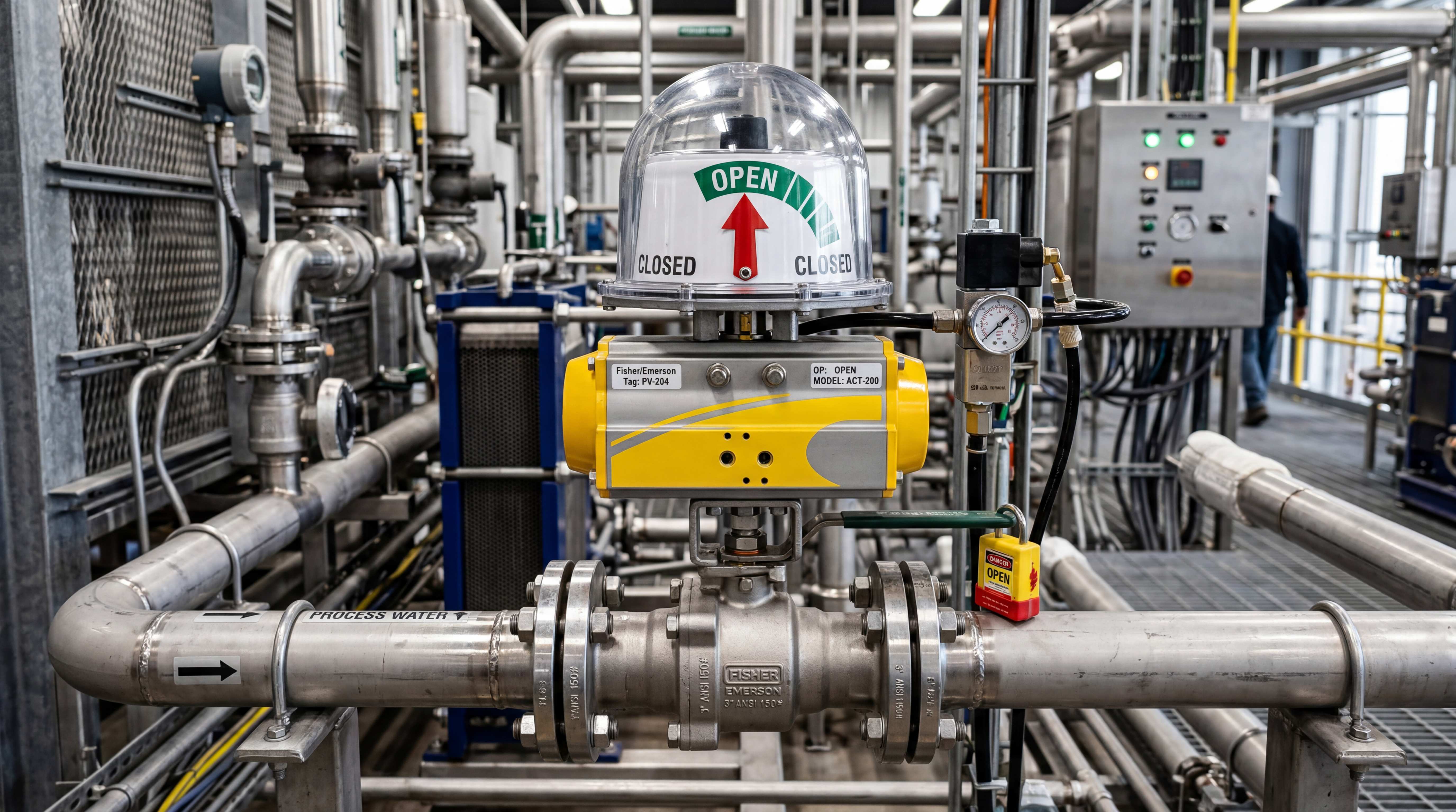
In automated systems, diverting valves should be paired with clear position feedback. The control system should know whether the valve is sending flow to path A or path B. A simple open/closed label may not describe the real state. Position names such as “filter,” “bypass,” “tank A” or “tank B” may be more meaningful for operators.
Mixing Ball Valve Applications

A mixing ball valve combines two incoming streams into one outlet. This is commonly associated with T-port ball valves, although the exact suitability depends on valve design and control requirements.
Mixing applications appear in temperature control, chemical blending, water treatment, cleaning systems, process dilution and utility systems. For example, a system may mix hot and cold water to reach a desired temperature. Another process may blend a chemical concentrate with water. A thermal management system may combine return flow and supply flow.
A T port ball valve can create a mechanical flow path that connects two inlets to one outlet. However, it is important to understand the difference between simple mixing and precise control. A standard T-port ball valve may allow mixing, but it may not provide accurate proportional control unless the valve and actuator are designed for modulation.
If the process requires precise ratio control, the engineer may need a modulating actuator, position feedback, flow sensors or a different valve design. In some cases, control valves may be better than standard ball valves. A ball valve can switch and route flow very well, but it is not always the best device for fine proportional mixing.
This is a common selection mistake. A buyer sees “mixing” and assumes any T port ball valve can accurately blend two streams. In reality, the valve may only connect the ports; it does not automatically control the mixing ratio. The control system must still measure and adjust flow if accuracy is required.
Multiport Ball Valve as a Piping Simplification Tool
A multiport ball valve can replace several individual valves in certain systems. This is one of the reasons 3-way ball valves are attractive in compact equipment and process skids.
In an OEM machine, space may be limited. A single electric 3 way ball valve can switch between operating modes without adding multiple valves, extra fittings and complicated piping. In a filtration skid, a 3-way valve may help switch between service and bypass. In a dosing system, it may select between supply and flushing paths. In a thermal system, it may redirect flow based on operating mode.
The benefit is not only fewer components. It can also reduce assembly time, leakage points, wiring complexity and maintenance confusion. A single actuator controlling one multiport ball valve may be easier to coordinate than two actuators controlling two separate valves.
However, this simplification only works when the flow pattern is correct. If the wrong L-port or T-port configuration is selected, the system may become more confusing rather than simpler. The valve may need a special rotation angle, a specific actuator stop arrangement or a custom porting diagram.
For this reason, multiport ball valve selection should be treated as part of system design, not as a last-minute purchasing decision. The valve should be included in the piping and instrumentation diagram, control sequence and maintenance plan.
Electric 3-Way Ball Valve in Automation Systems

An electric 3 way ball valve combines a 3-way valve body with an electric actuator. It is commonly used when a system needs automatic switching between flow paths and compressed air is not available or not preferred.
Electric 3-way valves are used in water treatment, HVAC, irrigation, lab equipment, small process skids, thermal control systems and OEM machines. They can connect to PLCs, relays, timers, sensors or building automation controllers.
The main advantage is integration. Electrical control is often already present in modern equipment. A motorized 3-way valve can be wired into the control panel and operated based on temperature, pressure, level, time or process mode.
But electric 3-way valves require careful position control. A 2-way valve may only need open and closed feedback. A 3-way valve may need feedback that clearly identifies which flow path is active. For example, a system may need to know whether the valve is in bypass mode or process mode. Generic “open” and “closed” indicators may not be enough.
Actuator rotation is another important issue. Some 3-way valves use 90-degree rotation between two positions. Others may require 180-degree rotation or multiple stop positions. The actuator must match the valve’s required motion. If the actuator only turns 90 degrees but the valve requires a different rotation to achieve the desired path, the assembly will not work correctly.
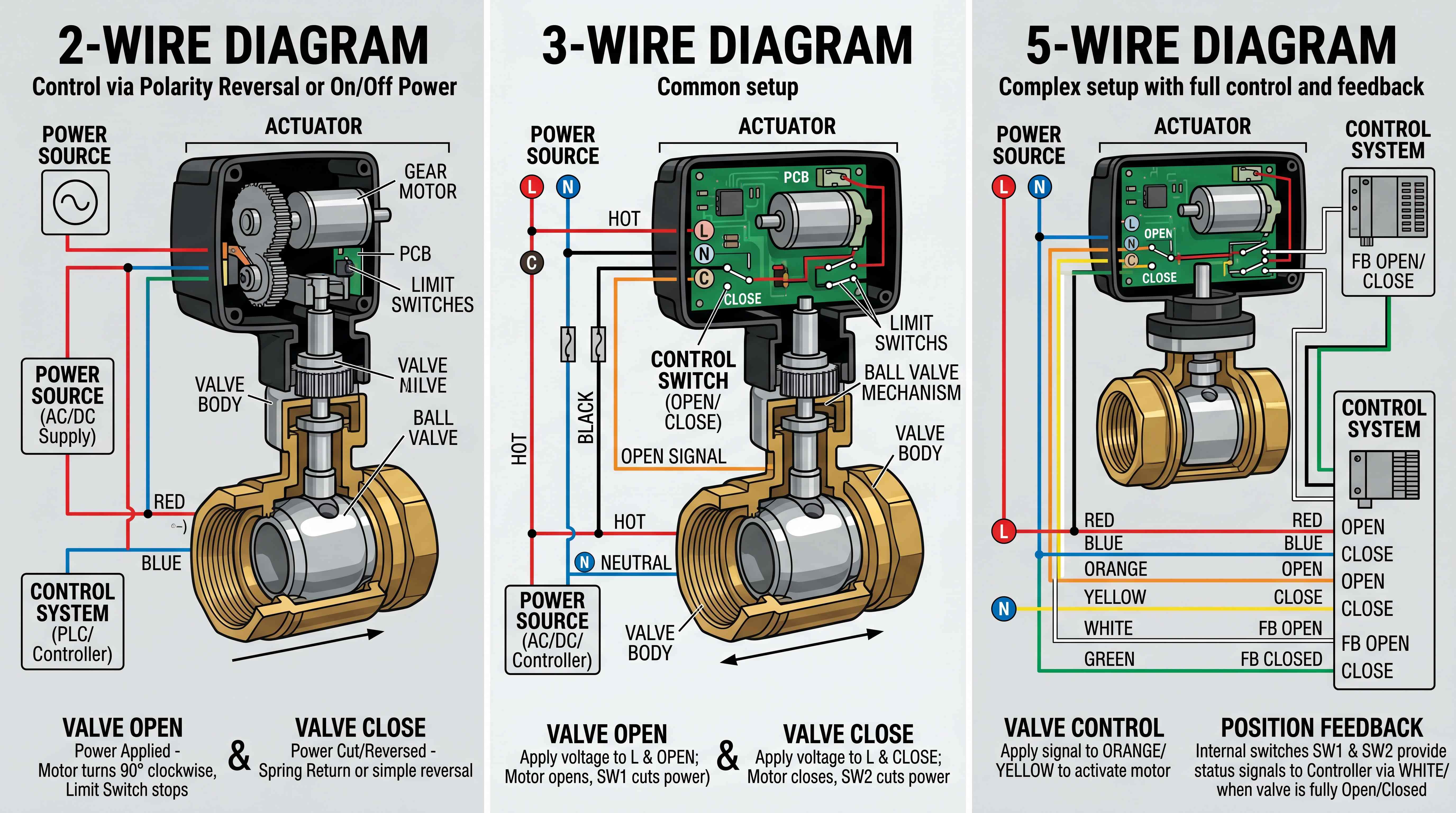
Before purchasing an electric 3 way ball valve, the buyer should confirm port diagram, voltage, control type, rotation angle, feedback signal, manual override, enclosure rating and fail behavior.
Pneumatic 3-Way Ball Valve in Industrial Plants
A pneumatic 3-way ball valve uses a pneumatic actuator to switch the flow path. It is common in industrial plants where compressed air is already available and where fast operation is needed.
Pneumatic actuation can be useful for larger 3-way valves because it can provide strong torque. It is also common in chemical processing, production lines, water treatment systems and factory automation. A pneumatic 3-way valve may use a double acting actuator or a spring return actuator depending on the required fail position.
Fail-safe behavior becomes more complex with 3-way valves. For a 2-way valve, fail close usually means the valve blocks the line. For a 3-way valve, fail position may mean connecting common to port A, connecting common to port B, or possibly moving to a blocked position depending on design. The safe state must be defined in process terms, not generic valve terms.
For example, a chemical system may require the valve to fail to recirculation instead of process feed. A cooling system may require the valve to fail to bypass. A drain system may require the valve to fail away from the drain line. These decisions should be made before actuator selection.
Pneumatic 3-way valves also require solenoid valves, air tubing, regulators and position feedback devices. The control system should display the actual process state, not only actuator state. Operators should be able to see whether flow is going to path A, path B or both if the valve design allows it.
Common Flow Direction Mistakes
One of the most common mistakes is buying a 3-way valve without checking whether it is L-port or T-port. The buyer may only specify size, material and connection type, then discover during installation that the flow pattern is wrong.
Another mistake is assuming that all 3-way valves have the same common port. The common port can vary by design. If the valve is installed in the wrong orientation, the actual flow path may not match the piping plan.
A third mistake is confusing diverting and mixing. A valve used for diverting one inlet to two outlets may not behave the same when used for mixing two inlets into one outlet. Pressure balance, backflow and internal porting must be considered.
A fourth mistake is using a standard 3-way valve for precise proportional control. A T-port valve can connect flow paths, but it does not automatically provide accurate mixing ratio or flow regulation. Control accuracy requires suitable valve characteristics and feedback.
A fifth mistake is ignoring actuator rotation. Manual 3-way valves may have handle positions that are easy to see, but automated valves depend on actuator stops and control signals. If the actuator rotation does not match the valve porting, the system may stop in the wrong position.
A sixth mistake is labeling the valve simply as open or closed. For a 3-way valve, “open” is not enough. The operator needs to know which ports are connected.
These mistakes are avoidable when the valve is selected from the flow diagram rather than from the product photo.
How to Read a 3-Way Ball Valve Flow Diagram

A 3-way ball valve flow diagram shows which ports are connected at each valve position. It may use arrows, port letters or simple line drawings to show the internal ball passage.
When reading the diagram, first identify the ports. They may be labeled A, B and C, or port 1, port 2 and port 3. Do not assume the center port is always common. Confirm it from the manufacturer’s diagram.
Next, identify the ball pattern. Is it an L port ball valve or a T port ball valve? The internal shape determines how many ports can be connected.
Then review each rotation position. At 0 degrees, which ports are connected? At 90 degrees, which ports are connected? At 180 degrees, is there another position? Are any ports blocked? Are all three ports connected in any position?
After that, compare the diagram with the process requirement. If the process needs to divert flow from inlet to outlet A or outlet B, the diagram should clearly show those two states. If the process needs mixing, the diagram should show whether both inlets can connect to the outlet.
Finally, consider actuator feedback. The control system should identify each useful valve position in process language. Instead of only saying position 1 and position 2, it may be better to label them as “process,” “bypass,” “drain,” “tank A” or “tank B.”
Reading the flow diagram carefully before installation can prevent expensive piping changes later.
Choosing Between L-Port and T-Port
Choose an L port ball valve when the system needs to switch between two flow paths and only one path should be active at a time. It is usually the better choice for diverting, source selection and simple two-position routing.
Choose a T port ball valve when the system needs to connect multiple ports in more flexible ways, such as mixing, distributing or allowing flow through more than one branch. It may also be useful when the process requires a shared flow path.
But the decision should not be based only on the words “diverting” or “mixing.” The actual port connection states matter. Some applications that appear to need a T-port valve may be better served by separate 2-way valves. Some applications that appear simple may need a custom 3-way port configuration.
The safest method is to draw the required flow states before selecting the valve. State one: which ports connect? State two: which ports connect? Failure state: which ports should connect or block? Maintenance state: does the valve need a special position?
Once these states are clear, the correct port pattern becomes much easier to identify.
Material and Connection Choices Still Matter
Flow pattern is critical, but it is not the only selection factor. A 3 way ball valve must still match the media, pressure, temperature and installation environment.
For water and general service, brass or stainless steel may be common. For chemical applications, stainless steel, PVC, CPVC, PP or PVDF may be considered depending on chemical compatibility. For food, beverage or sanitary systems, stainless steel and suitable sealing materials may be required.
Seat material is also important. PTFE is common, but not every seat material is suitable for every pressure, temperature or chemical condition. Seals must also match the media.
Connection type should match the piping system. Threaded, flanged, welded, clamp and union connections may all be used depending on application. In automated systems, maintenance access should be considered. If the actuator blocks access to bolts or fittings, service may become difficult.
For electric 3 way ball valve applications, actuator enclosure rating, voltage, cable entry and control interface must be checked. For pneumatic versions, air pressure, tubing, solenoid valve and feedback box must be selected correctly.
A good 3-way valve selection combines flow logic with mechanical, material and control compatibility.
When a 3-Way Valve Is Not the Best Choice
A 3-way valve is useful, but it is not always the best solution.
If the process requires complete independent control of multiple lines, separate 2-way valves may be better. A 3-way valve mechanically links flow paths together. This is useful for switching but may limit flexibility.
If the process requires precise proportional control between two streams, a standard T-port ball valve may not be accurate enough. Dedicated control valves, modulating valves or flow control loops may be needed.
If maintenance teams need to isolate multiple branches independently, separate valves may make troubleshooting easier. A single multiport ball valve can simplify piping but may also make the system harder to understand if not clearly labeled.
If failure behavior must isolate all lines, a standard 3-way valve may not provide the required blocked state. Some designs allow all ports connected or one path open in failure. Special valve designs may be needed.
If the system has high safety risk, the design should be reviewed carefully. A wrong 3-way valve position can connect incompatible fluids, open a drain path, bypass treatment or send flow to the wrong equipment.
The goal is not to use a 3-way valve whenever possible. The goal is to use it when it improves system function and reduces operational risk.
A Practical Selection Checklist
Before choosing a 2 way ball valve or 3 way ball valve, define the process function. Does the valve need to isolate, divert, mix, bypass, select a source or distribute flow?
Then draw the required flow states. For each operating mode, mark which ports should be connected and which should be blocked. This is especially important for a 3-way valve.
Next, choose the internal ball pattern. Use an L port ball valve for simple switching between two paths. Use a T port ball valve when the system needs mixing, sharing or multi-port connection.
After that, confirm flow direction and pressure relationship. Check whether backflow can occur, whether check valves are needed and whether pressure from one branch can push into another branch.
Then select valve material, seat material and connection type based on media, pressure, temperature and installation conditions.
Next, decide whether the valve will be manual or automated. If automated, choose electric or pneumatic actuation based on utilities, cycle frequency, torque, control signal and fail-safe needs.
Then confirm actuator rotation and feedback. A 3-way automated valve should clearly identify each useful flow position. Operators and control systems should know the actual path, not just open or closed.
Finally, review maintenance and labeling. Port labels, flow arrows, actuator position indicators and control panel names should match the process. Clear labels reduce operator error.
Final Thoughts
A 2 way ball valve and a 3 way ball valve may belong to the same ball valve family, but they solve different flow control problems. A 2-way valve is best for simple open-close isolation. A 3-way valve is best when the system needs to route, divert, mix or switch flow between multiple paths.
The most important difference is the internal ball valve flow pattern. An L port ball valve usually supports switching and diverting. A T port ball valve offers more flexible port connections and can support mixing or distribution. But more flexibility also means more risk if the valve is misunderstood.
In valve automation, these details become even more important. An electric 3 way ball valve or pneumatic 3-way valve must match not only the pipeline but also the control logic. The actuator must rotate to the correct positions, feedback must identify the actual flow path, and the failure state must be safe for the process.
The best selection method is simple: draw the flow first, then choose the valve. Do not start with the product image. Do not assume all 3-way valves are the same. Do not treat “open” and “closed” as enough information for a multiport ball valve.
A well-selected 3-way ball valve can simplify piping, reduce component count and improve automation efficiency. A poorly selected one can create wrong flow paths, process errors and expensive rework. In industrial flow control, the internal passage inside the ball often matters more than the valve body you see from outside.
Focused FAQ
What is the difference between a 2 way ball valve and a 3 way ball valve?
A 2 way ball valve has two ports and is mainly used for open-close flow control. A 3 way ball valve has three ports and can divert, mix or switch flow paths depending on the internal ball valve flow pattern.
What is an L port ball valve used for?
An L port ball valve is usually used for diverting or source selection. It connects a common port to one of two other ports, making it suitable for switching flow between two paths.
What is a T port ball valve used for?
A T port ball valve is used when the system needs more flexible port connections. It can support mixing, distribution or multiport flow arrangements depending on the valve position and port configuration.
Is a 3 way ball valve always better than a 2 way ball valve?
No. A 3 way ball valve is only better when the system needs routing, diverting or mixing. If the application only needs simple shut-off, a 2 way ball valve is usually simpler and more reliable.
What does 3 way ball valve flow direction mean?
3 way ball valve flow direction refers to which ports are connected in each valve position. It depends on whether the valve has an L-port or T-port ball design and how the valve is installed in the pipeline.
Can a 3 way ball valve be used as a mixing ball valve?
Yes, some 3 way ball valves, especially T-port designs, can be used for mixing two streams into one outlet. However, precise proportional mixing may require a modulating actuator, flow sensors or a dedicated control valve.
Can a 3 way ball valve be used as a diverting ball valve?
Yes. An L port ball valve is commonly used as a diverting ball valve because it can direct one inlet flow to one of two outlets.
What is an electric 3 way ball valve?
An electric 3 way ball valve is a 3-way ball valve operated by an electric actuator. It is used to automate flow routing in water treatment, HVAC, irrigation, process skids and OEM equipment.
Why is port labeling important for 3-way ball valves?
Port labeling is important because the common port and flow path may vary by valve design. Incorrect port identification can send flow to the wrong branch or connect lines unintentionally.
How do I choose between L-port and T-port ball valves?
Choose an L-port ball valve for simple switching or diverting between two paths. Choose a T-port ball valve when the application needs mixing, distribution or more flexible multiport connection. The best method is to draw the required flow states before selecting the valve.
#2WayBallValve #3WayBallValve #LPortBallValve #TPortBallValve #BallValveFlowDirection #DivertingBallValve #MixingBallValve #MultiportBallValve #Electric3WayBallValve #BallValveFlowPattern #ValveAutomation #BallValveAutomation #IndustrialComponents #FlowControl #ProcessAutomation