Turbo Intake, Charge Pipe, and Intercooler Piping: Understanding the Air Path in Boosted Engines
Why Turbocharged Engines Need a Different Intake Conversation
A turbocharged engine changes the meaning of an intake system. In a naturally aspirated engine, the intake path mainly guides air from the filter to the throttle body or intake manifold. In a turbocharged engine, the air path is divided into several zones with different pressure, temperature and mechanical requirements. The turbo intake pipe, turbo inlet pipe, intercooler piping and charge pipe all work together, but they do not perform the same job.
This is why turbo intake discussions should not be limited to the question of whether a cold air intake adds horsepower. In a boosted engine, airflow is not only pulled by engine vacuum. It is also compressed by the turbocharger. Once air enters the compressor, it becomes hotter and pressurized. After that, the system must manage boost pressure, charge temperature, pressure drop, coupler strength, pipe routing, sensor placement and throttle response.
A simple tube-and-filter view is not enough. A turbocharged intake system is an air management network. One weak connection, restrictive bend or poorly clamped silicone coupler can affect the entire system. A cracked charge pipe can create boost leaks. A narrow turbo inlet pipe can limit compressor efficiency. Poor intercooler piping can increase pressure loss. A badly routed hot side piping section can increase heat exposure. A loose cold side piping connection can cause inconsistent boost and drivability issues.
For the Metal Pipes & Bending category, turbocharged intake systems are especially important because they require more than basic tubing. Aluminum intercooler pipe, mandrel bends, bead-rolled ends, welded sensor bungs, reinforced silicone couplers and T-bolt clamps all become part of the product value. In this field, pipe geometry and connection reliability are not small details. They are the foundation of performance and durability.
The Complete Air Path in a Turbocharged Engine

To understand turbo intake pipe and charge pipe design, it helps to follow the air from the beginning to the end.
Air first enters through the filter or airbox. It then moves into the turbo intake pipe or turbo inlet pipe. This section is before the compressor, so it is usually not under boost pressure. However, it still needs to provide enough airflow to the turbocharger. If the turbo inlet pipe is restrictive, the compressor has to work harder to draw in air.
The air then enters the compressor side of the turbocharger. The compressor wheel accelerates and compresses the air. Compression increases air pressure, but it also raises air temperature. Hot compressed air is less dense than cooled compressed air, so the system normally sends this air through an intercooler.
From the turbocharger compressor outlet, the air travels through hot side piping. This is the pipe section between the turbo outlet and the intercooler inlet. It is called hot side piping because the air has just been compressed and is usually hot.
Inside the intercooler, heat is transferred away from the compressed air. After leaving the intercooler, the air travels through cold side piping. This section leads toward the throttle body or intake manifold. In many applications, the final pipe section before the throttle body is called the charge pipe. Some markets also use the term boost pipe to describe similar pressurized air tubes.
Finally, the cooled and pressurized air enters the intake manifold and reaches the cylinders. Every section of this air path influences performance. A turbo piping kit is only as strong as its weakest connection.
Turbo Inlet Pipe: Feeding the Compressor

The turbo inlet pipe is the section that feeds air into the compressor inlet. It is often overlooked because it is before the turbocharger and may not look as dramatic as intercooler piping. However, it plays a major role in compressor efficiency.
The turbocharger needs a stable air supply. If the inlet path is narrow, sharply bent or poorly shaped, the compressor may experience restriction before it can do its job. This can reduce airflow potential, especially at higher boost levels or with larger turbochargers. A restrictive turbo inlet pipe may not always create an obvious failure, but it can limit the system’s ability to breathe.
A good turbo intake pipe should provide enough diameter for the target airflow, maintain smooth bends and avoid sudden transitions. It should also connect securely to the turbocharger compressor inlet. In some engines, the inlet pipe must fit in a very tight space, which makes geometry difficult. This is where proper pipe bending and material selection become important.
Material choice depends on the application. Aluminum is common for performance turbo inlet pipes because it can be formed, welded and finished cleanly. Reinforced silicone is also used because it provides flexibility and can fit around tight engine bay packaging. Plastic is common in OEM applications, but aging and heat exposure may lead some owners to replace factory plastic inlets with upgraded metal or silicone versions.
The turbo inlet pipe is not simply an intake accessory. It is the first performance gate before the compressor. If it is poorly designed, every downstream component has to work with a compromised air supply.
Compressor Outlet and Hot Side Piping
After air passes through the compressor, it exits at higher pressure and higher temperature. The first pipe section after the turbocharger is often called hot side piping. This section connects the compressor outlet to the intercooler inlet.
Hot side piping must handle several challenges at once. First, it must carry pressurized air. Second, it must tolerate elevated temperature. Third, it must fit around the engine, radiator, fans, frame rails or other components. Fourth, it must stay sealed under boost pressure and engine movement.
Because this section carries compressed air, connection quality becomes very important. A weak clamp, short coupler or smooth pipe end without bead rolling may slip under boost. A small leak can reduce pressure, slow response and make tuning inconsistent. In higher-boost applications, a poor connection may fail suddenly.
Aluminum intercooler pipe is widely used for hot side piping because it is lightweight, rigid and suitable for mandrel bending. It can be welded with sensor bungs, brackets or mounting tabs. However, aluminum conducts heat, so pipe routing and heat exposure should be considered. If the hot side pipe runs near the exhaust manifold or turbine housing, thermal shielding may be useful.
Hot side piping should be as direct as practical, but direct does not mean careless. Sharp bends and abrupt diameter changes can increase pressure drop. The pipe should route efficiently while preserving service access and avoiding rubbing points. In professional turbo piping kit design, the hot side pipe is designed for both airflow and installation reliability.
Intercooler Piping and the Role of the Intercooler

The intercooler is the heat exchanger that cools compressed air before it enters the engine. Intercooler piping connects the turbocharger, intercooler and throttle body. The pipe system must move air efficiently while maintaining boost pressure.
A common mistake is thinking of the intercooler as the only important part of the system. The intercooler core matters, but the piping around it also matters. Poor intercooler piping can create unnecessary pressure drop, slow boost response or cause fitment problems. Even a high-quality intercooler cannot fully compensate for poorly designed pipes and weak connections.
Intercooler piping layout depends on vehicle design. Some vehicles use a front-mount intercooler, which requires longer pipe routing from the turbocharger to the front of the vehicle and back to the engine. Others use a top-mount intercooler or side-mount intercooler with shorter paths. Each layout has trade-offs.
Longer piping can increase total air volume in the system, which may affect response. Shorter piping may improve response but may be limited by heat exposure or intercooler size. Larger pipe diameter may reduce restriction at high airflow, but oversized tubing can increase volume and packaging difficulty. This is why intercooler piping design is always a balance.
For manufacturers and B2B buyers, intercooler piping is a strong product category because it requires precise bending, good welding, repeatable fitment and reliable coupler connections. It is not a generic pipe. It is a performance airflow component.
Cold Side Piping and Charge Pipe Function
After the air leaves the intercooler, it travels through cold side piping toward the engine. This air is still pressurized, but it should be cooler than the air coming directly from the compressor. The final section before the throttle body is often called the charge pipe.
The charge pipe is especially important because it connects the intercooler outlet or cold side pipe to the throttle body or intake manifold. It may also include sensor ports, blow-off valve or bypass valve connections, methanol injection ports or other fittings depending on the application.
In many modern turbocharged vehicles, factory charge pipes are made from plastic. This can work well for standard power levels, but plastic charge pipes may crack or fail as they age or when boost pressure increases. This is one reason upgraded aluminum charge pipe products are popular in the aftermarket.
A quality charge pipe should maintain a smooth airflow path, resist pressure, fit accurately and provide secure connections. If it includes a sensor boss, the location and angle should be correct. If it includes a blow-off valve flange, the weld quality and sealing surface must be reliable. If it connects to a silicone coupler, the pipe end should be bead rolled to reduce the chance of slipping.
Cold side piping and charge pipe design also affect serviceability. The pipe should not block access to critical components more than necessary. Clamps should be reachable. Sensors should be accessible. In professional product design, installation time and maintenance access are part of the value.
Boost Pipe, Charge Pipe, and Intercooler Pipe: Understanding the Terms
The terminology around turbo piping can be confusing. Different markets and brands may use the same term differently. “Boost pipe” is often used as a broad term for pipes that carry pressurized air. “Charge pipe” usually refers to the pressurized pipe that carries cooled air toward the throttle body. “Intercooler piping” can refer to both hot side and cold side pipes around the intercooler.
A turbo inlet pipe is different because it is before the compressor. It is not normally pressurized in the same way as a charge pipe. Its job is to feed the turbocharger, not carry compressed air from the turbocharger.
Hot side piping usually means the pipe between the compressor outlet and the intercooler inlet. Cold side piping usually means the pipe between the intercooler outlet and the throttle body or intake manifold. Both are pressurized, but they operate at different temperatures.
These terms matter because buyers often search for specific parts. A customer looking for a charge pipe may not be looking for a turbo intake pipe. A shop looking for an intercooler piping kit may need both hot side and cold side sections. A distributor sourcing aluminum intercooler pipe may need universal tubing, while a tuning brand may need vehicle-specific turbo piping kits.
For content strategy, clear definitions help the site capture long-tail traffic and build authority. For B2B sourcing, clear terminology reduces misunderstanding between buyer and supplier.
Pipe Diameter in Turbo Piping
Turbo piping diameter must be selected carefully. Bigger is not always better. A pipe that is too small can create restriction and pressure drop. A pipe that is too large can increase system volume, complicate routing and sometimes reduce response.
The correct diameter depends on turbo size, boost pressure, power target, engine displacement and available space. A small turbo setup may not need very large piping. A high-power build may require larger aluminum intercooler pipe to support airflow. The pipe diameter should match the system’s actual airflow demand, not simply the largest size that can fit.
Hot side and cold side piping may not always use the same diameter. Some systems use smaller hot side piping for response and larger cold side piping for flow. Others use consistent sizing for simplicity and availability. There is no single rule for every application.
Pipe diameter also interacts with bend quality. A large pipe with poor bends may not perform as well as a correctly sized pipe with smooth routing. A tight bend, crushed section or abrupt transition can become a local restriction. Mandrel bends help maintain consistent internal diameter through curves, which is especially useful for turbo piping kits.
For B2B buyers, the important point is to evaluate diameter together with geometry. Product quality is not only the nominal pipe size. It is the complete airflow path.
Bend Design, Pressure Drop, and Response
Pressure drop is one of the key concerns in turbo piping. When air moves through pipes, bends, couplers and intercooler cores, some pressure is lost. The turbocharger may need to work harder to maintain target boost at the engine. Excessive pressure drop can reduce efficiency and increase heat.
Bend design affects pressure drop. Smooth, gradual bends usually create less disturbance than sharp bends. Mandrel-bent piping helps maintain a consistent internal cross-section. Poorly formed bends can reduce effective flow area and create turbulence.
In compact engine bays, bends are unavoidable. The goal is not to eliminate all bends, but to design them intelligently. A shorter route with several sharp bends may not be better than a slightly longer route with smoother curves. The best layout balances pipe length, bend radius, heat exposure, service access and fitment.
Response is also affected by volume and flow resistance. Very long or oversized piping can increase the air volume that must be pressurized. Restrictive piping can slow airflow and increase compressor workload. A well-designed turbo piping kit supports both flow and response.
This is where Metal Pipes & Bending expertise becomes valuable. The difference between a basic pipe and a high-quality performance pipe is often found in bend consistency, internal smoothness, welding accuracy and fitment control.
Couplers, Clamps, and Bead-Rolled Ends
Turbo piping does not fail only because of the main pipe. It often fails at the connections. Silicone couplers, clamps and pipe ends are critical to boost reliability.
A silicone coupler connects rigid pipe sections while allowing some movement. Engines move under load, and rigid pipes cannot absorb all vibration or shifting. Silicone couplers help maintain alignment and reduce stress. However, they must be properly sized and reinforced. Thin or low-quality couplers may expand, tear or slip under pressure.
Clamps are equally important. Worm gear clamps may work in lower-pressure applications, but T-bolt clamps are often preferred for higher boost because they apply stronger and more even clamping force. The clamp must match the coupler and pipe diameter. Over-tightening can damage silicone, while under-tightening can cause leaks.
Bead-rolled pipe ends are a major reliability feature. A bead roll creates a raised lip near the pipe end, helping the coupler stay in place under pressure. Without bead rolling, a smooth aluminum pipe can allow the coupler to slip off, especially during boost spikes or engine movement.
For B2B buyers, connection hardware should never be treated as low-priority accessories. A turbo piping kit with good pipes but weak couplers and clamps can still fail in the field. The complete kit must be evaluated as a system.
Sensor Ports, Blow-Off Valve Flanges, and Fittings
Turbo piping often includes more than simple tubes. It may include sensor ports, blow-off valve flanges, bypass valve connections, vacuum fittings or methanol injection bungs. These details must be placed and manufactured accurately.
A sensor port must be positioned where it can read stable conditions and where the wiring can connect safely. If the sensor is mounted at the wrong angle or too close to a turbulent area, readings may become less reliable. If the boss is poorly welded, leaks can occur.
Blow-off valve or bypass valve flanges must be flat, strong and properly sealed. Poor welding or flange distortion can create leaks. The valve location should also support proper function and service access. In some systems, valve placement affects sound, response and compressor surge behavior.
Additional fittings should not create unnecessary internal obstruction. A poorly installed bung may protrude into the airflow path. A weld bead inside the pipe may disturb flow. These small details matter in high-quality fabrication.
For manufacturers, these features require process control. Welding accuracy, fixture design and inspection standards help ensure each part is consistent. For buyers, the presence of clean, properly placed fittings is a sign of a more professionally developed product.
Material Choices for Turbo Piping
Turbo piping materials must handle airflow, pressure, heat and installation stress. Aluminum is the most common material for aftermarket intercooler piping and charge pipes because it is lightweight, formable and relatively easy to fabricate. It can be mandrel bent, welded and bead rolled.
Stainless steel can offer higher strength and heat resistance, but it is heavier and often more expensive to process. It may be used in custom or specialized applications but is less common for general intercooler piping kits.
Silicone is used for couplers, elbows and flexible sections. Reinforced silicone can also be used as a pipe section in some turbo inlet applications. Its flexibility makes it valuable in tight spaces and areas with engine movement.
Plastic is common in OEM charge pipes and intake tubes, but it can become a weak point when boost is increased or the part ages. Many aftermarket upgrades replace factory plastic charge pipes with aluminum versions for improved durability.
Carbon fiber may be used in premium intake and charge systems, but it requires careful engineering. It can provide lightweight and visual value, but pressure, heat and connection design must be validated.
The best turbo piping material strategy often combines materials: aluminum pipes for structure, silicone couplers for movement, strong clamps for sealing and heat protection where needed. Material choice should always match the operating zone.
Heat Management in Turbo Piping
Turbocharged systems generate heat at several points. The turbocharger compressor heats the intake air during compression. The turbine side and exhaust manifold add radiant heat to the engine bay. The intercooler removes heat from compressed air, but the piping before and after the intercooler can still be affected by surrounding temperatures.
Hot side piping naturally carries hotter air. It should be routed efficiently and protected from unnecessary external heat when possible. Cold side piping should avoid heat sources to preserve the temperature drop created by the intercooler. If cooled air passes through a pipe routed near an exhaust component, some of the intercooling benefit may be reduced.
Heat shielding and thermal barriers may be useful in tight engine bays. Reflective sleeves, heat wrap, air guides and shielding panels can reduce heat exposure. However, heat management should begin with routing. Insulation should support good design, not compensate for poor layout.
Intercooler placement also matters. A front-mount intercooler may receive strong airflow but requires longer piping. A top-mount intercooler may use shorter piping but may face heat soak from the engine bay. Different layouts create different piping challenges.
For B2B suppliers, heat management opens opportunities for upgraded product bundles: aluminum intercooler pipe with silicone couplers, thermal sleeves, heat shields and installation hardware. A complete solution can offer more value than individual pipes.
Common Failure Points in Turbo Intake and Charge Systems
Turbo piping systems can fail in predictable ways. The most common issue is a boost leak. This can happen at a loose coupler, cracked charge pipe, damaged gasket, weak clamp or poorly sealed fitting. A boost leak may cause loss of power, slower spool, rich or lean behavior, unusual sounds or check engine lights.
Another common failure is coupler blow-off. This happens when boost pressure pushes a silicone coupler off a pipe end. Smooth pipe ends, weak clamps or insufficient pipe engagement can contribute to this problem. Bead-rolled ends and correct clamp selection reduce the risk.
Plastic charge pipe cracking is also common in some applications, especially as vehicles age or boost levels increase. Heat cycling, pressure and vibration can weaken plastic parts over time. Aluminum charge pipe upgrades are often marketed as reliability improvements.
Pipe rubbing is another issue. If a pipe contacts the body, radiator support, fan shroud or engine component, vibration can wear through the pipe or nearby part. Proper brackets and clearance checks are important.
Sensor and fitting leaks can also occur. A poorly welded boss, loose plug or damaged O-ring can create small but significant leaks. These issues are sometimes harder to diagnose because the main pipes may appear intact.
A strong turbo piping kit should be designed to prevent these failure points before installation.
Universal Turbo Piping Kits vs Vehicle-Specific Kits

Universal turbo piping kits are popular for custom builds, engine swaps and fabrication shops. They usually include straight pipes, bends, silicone couplers and clamps. The advantage is flexibility. The installer can cut, route and assemble the system based on the project.
The disadvantage is that universal kits require skill. The installer must choose pipe routes, cut accurately, manage sensor placement, bead roll pipe ends or secure connections properly. A universal kit can work well in experienced hands but may be challenging for ordinary users.
Vehicle-specific turbo piping kits are designed for a particular engine and chassis. They usually offer better fitment, shorter installation time and more predictable results. They may include brackets, sensor bungs, valve flanges and correct couplers. The trade-off is higher development cost and less flexibility.
For B2B suppliers, both markets are valuable. Universal aluminum intercooler pipe kits serve fabricators and tuning shops. Vehicle-specific turbo piping kits serve retail brands, distributors and end users who want direct installation. The business model determines the product strategy.
A strong supplier may offer both: universal tubing components for fabrication channels and engineered vehicle-specific kits for aftermarket brands.
Manufacturing Requirements for High-Quality Turbo Piping

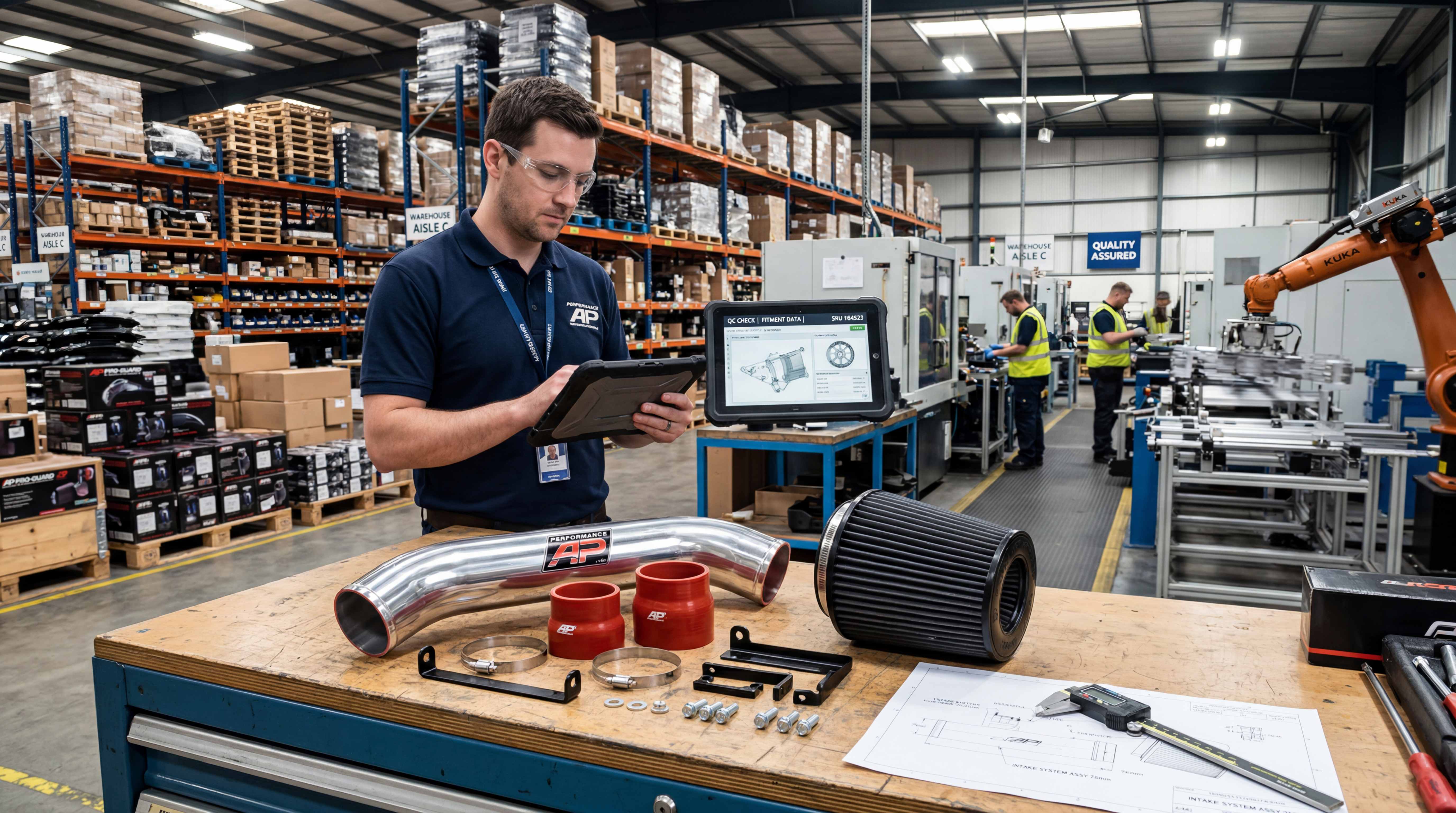
High-quality turbo piping requires more than cutting and welding tubes. It requires dimensional control, repeatable bending, clean welding, accurate fixtures, proper bead rolling, surface finish consistency and packaging protection.
Bend accuracy is critical. A small angle error can cause fitment problems in a tight engine bay. Pipe rotation must be controlled. End length must be consistent. Bracket location must match mounting points. Sensor bungs and valve flanges must be placed correctly.
Welding quality matters for both strength and sealing. Poor welds can crack or leak. Internal weld protrusion should be minimized. Flanges should remain flat after welding. For aluminum piping, welding consistency is also part of visual quality.
Bead rolling should be consistent. Too small a bead may not hold the coupler well. Too aggressive a bead may make installation difficult or damage silicone. The pipe end should be clean and smooth.
Surface finish depends on product positioning. Polished aluminum looks premium but requires protection. Brushed or powder-coated finishes may be more durable in some markets. Black-coated pipes can look OEM-like and hide dirt. Finish quality should be consistent across batches.
Packaging should protect visible surfaces and small components. A turbo piping kit includes pipes, couplers, clamps, fittings and sometimes brackets. Missing hardware creates customer frustration. Organized packaging improves installation experience and brand trust.
What B2B Buyers Should Ask Before Sourcing Turbo Piping
B2B buyers should evaluate turbo piping suppliers with technical questions, not only price questions.
They should ask what materials are available, what wall thickness is used, whether mandrel bending is supported, whether bead rolling is available, what welding process is used and how fitment is verified. They should also ask about surface finish options, packaging standards and inspection methods.
For vehicle-specific kits, buyers should ask whether the supplier has test-fit the product on the target vehicle. They should check whether the kit includes all couplers, clamps, brackets, sensor fittings and installation hardware. They should also verify whether different vehicle trims or model years require different routing.
For universal kits, buyers should confirm pipe diameters, bend angles, coupler sizes, clamp types and material thickness. Universal kits should be clearly labeled so fabricators can select parts easily.
Buyers should also ask about batch consistency. Turbo piping is installation-sensitive. A supplier that cannot maintain dimensions can create serious fitment problems. Sample quality alone is not enough. Production control matters.
A professional supplier should understand airflow, boost pressure, heat, fitment and aftermarket distribution needs. Turbo piping is not a commodity tube category when sold into performance markets.
Final Perspective: Turbo Piping Is an Air Management System

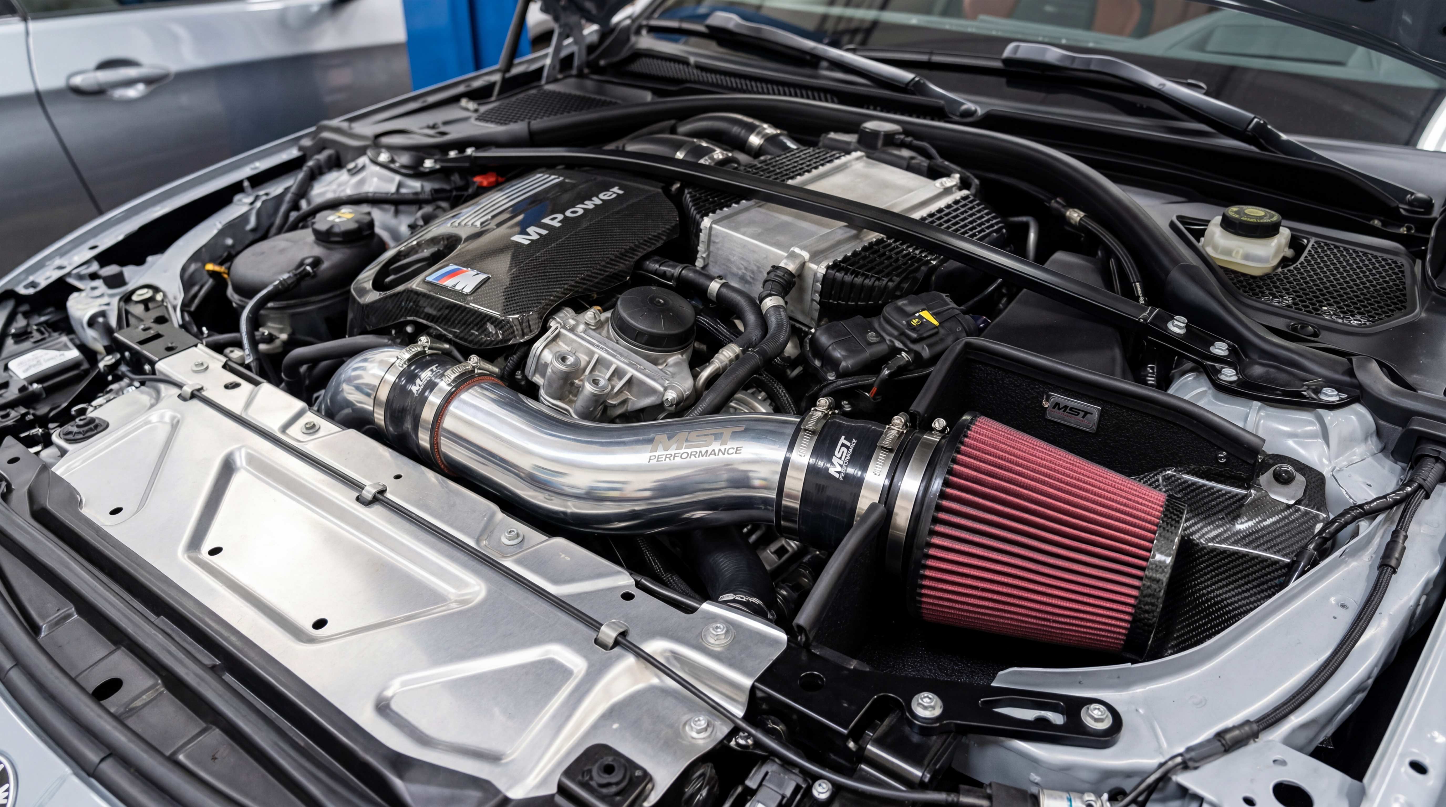
A turbocharged intake system is not one pipe. It is a connected air management system that begins at the filter, feeds the turbo inlet pipe, passes through the compressor, moves through hot side piping, cools in the intercooler, travels through cold side piping and enters the engine through the charge pipe.
Each section has a different job. The turbo intake pipe feeds the compressor. The hot side piping carries hot compressed air to the intercooler. The intercooler piping must manage pressure drop and routing. The cold side piping carries cooled boost toward the engine. The charge pipe must maintain sealing, sensor compatibility and throttle body fitment.
For drivers, understanding these sections helps diagnose problems and choose upgrades more intelligently. For fabricators, it improves custom turbo piping design. For B2B buyers, it provides a stronger framework for evaluating products and suppliers. For manufacturers, it highlights where real value is created: smooth bends, correct diameter, durable materials, bead-rolled ends, reinforced silicone couplers, strong clamps, accurate fittings and consistent production.
In turbocharged engines, airflow is not only about volume. It is about pressure, temperature, response and reliability. A good turbo piping kit does not simply connect parts together. It controls the path of boosted air from the compressor to the cylinders.
Focused FAQ
What is a turbo intake pipe?
A turbo intake pipe carries air from the filter or airbox to the turbocharger compressor inlet. It is before the compressor and helps feed the turbo with stable airflow. A restrictive turbo intake pipe can limit compressor efficiency and airflow potential.
What is a turbo inlet pipe?
A turbo inlet pipe is the pipe connected directly to the compressor inlet of the turbocharger. It may be made from aluminum, silicone, plastic or carbon fiber depending on the application. Its job is to reduce restriction before the turbo.
What is a charge pipe?
A charge pipe is a pressurized pipe that carries compressed and usually cooled air toward the throttle body or intake manifold. It is commonly found after the intercooler in turbocharged engines.
What is intercooler piping?
Intercooler piping connects the turbocharger, intercooler and engine. It usually includes hot side piping from the turbo to the intercooler and cold side piping from the intercooler to the throttle body or intake manifold.
What is the difference between hot side piping and cold side piping?
Hot side piping carries hot compressed air from the turbocharger compressor outlet to the intercooler. Cold side piping carries cooled compressed air from the intercooler toward the engine. Both sections must handle boost pressure, but they operate at different temperatures.
Is aluminum intercooler pipe better than plastic?
Aluminum intercooler pipe is often preferred in performance applications because it is rigid, durable, formable and suitable for bead-rolled ends and welded fittings. Plastic can work in OEM systems, but it may crack or fail when aged or exposed to higher boost pressure.
Why are silicone couplers used in turbo piping?
Silicone couplers connect rigid pipe sections while absorbing engine movement and vibration. Reinforced silicone couplers are important in turbo piping because they must handle pressure, temperature and repeated movement.
Why do turbo piping kits need bead-rolled ends?
Bead-rolled ends help prevent silicone couplers from slipping off under boost pressure. They create a raised lip that improves hose retention when used with proper clamps.
What causes boost leaks in charge pipes?
Boost leaks can be caused by loose clamps, damaged silicone couplers, cracked charge pipes, poor welds, leaking sensor fittings or weak pipe connections. A boost leak can reduce power, slow response and cause drivability problems.
What should B2B buyers check when sourcing turbo piping kits?
B2B buyers should check material, wall thickness, mandrel bend quality, bead-rolled ends, coupler strength, clamp type, weld quality, sensor boss accuracy, fitment validation, surface finish, packaging and batch consistency. A reliable turbo piping kit must manage airflow, boost pressure, heat and installation quality together.
#TurboIntakePipe #ChargePipe #IntercoolerPiping #TurboInletPipe #BoostPipe #HotSidePiping #ColdSidePiping #SiliconeCoupler #TurboPipingKit #AluminumIntercoolerPipe #BoostPressure #PerformancePiping #MetalPipesAndBending