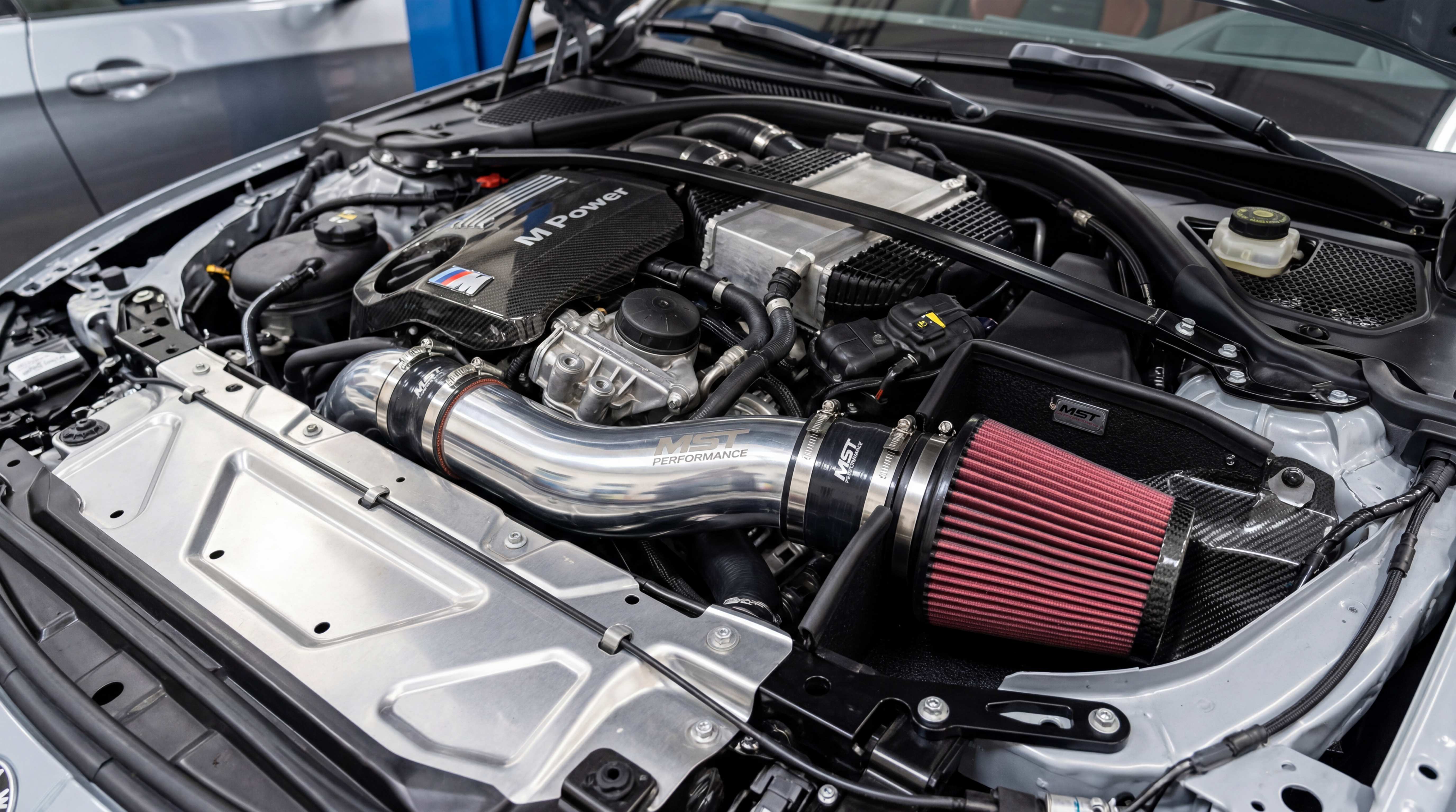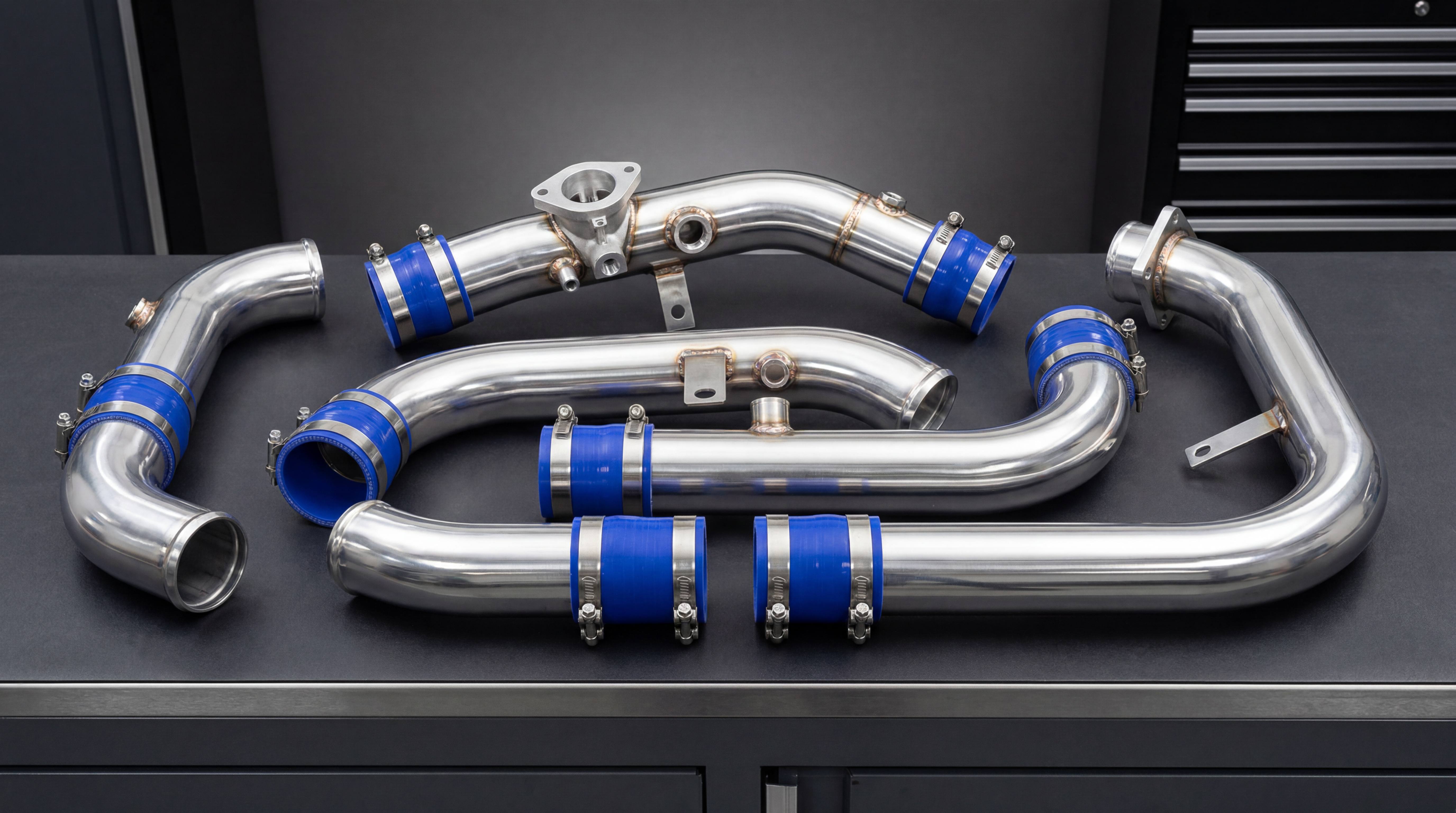
MAF Sensor, MAP Sensor, and ECU Tuning: Why Intake Upgrades Are Not Just About Airflow
Modern Intake Systems Are Controlled by Sensors, Not Just Pipes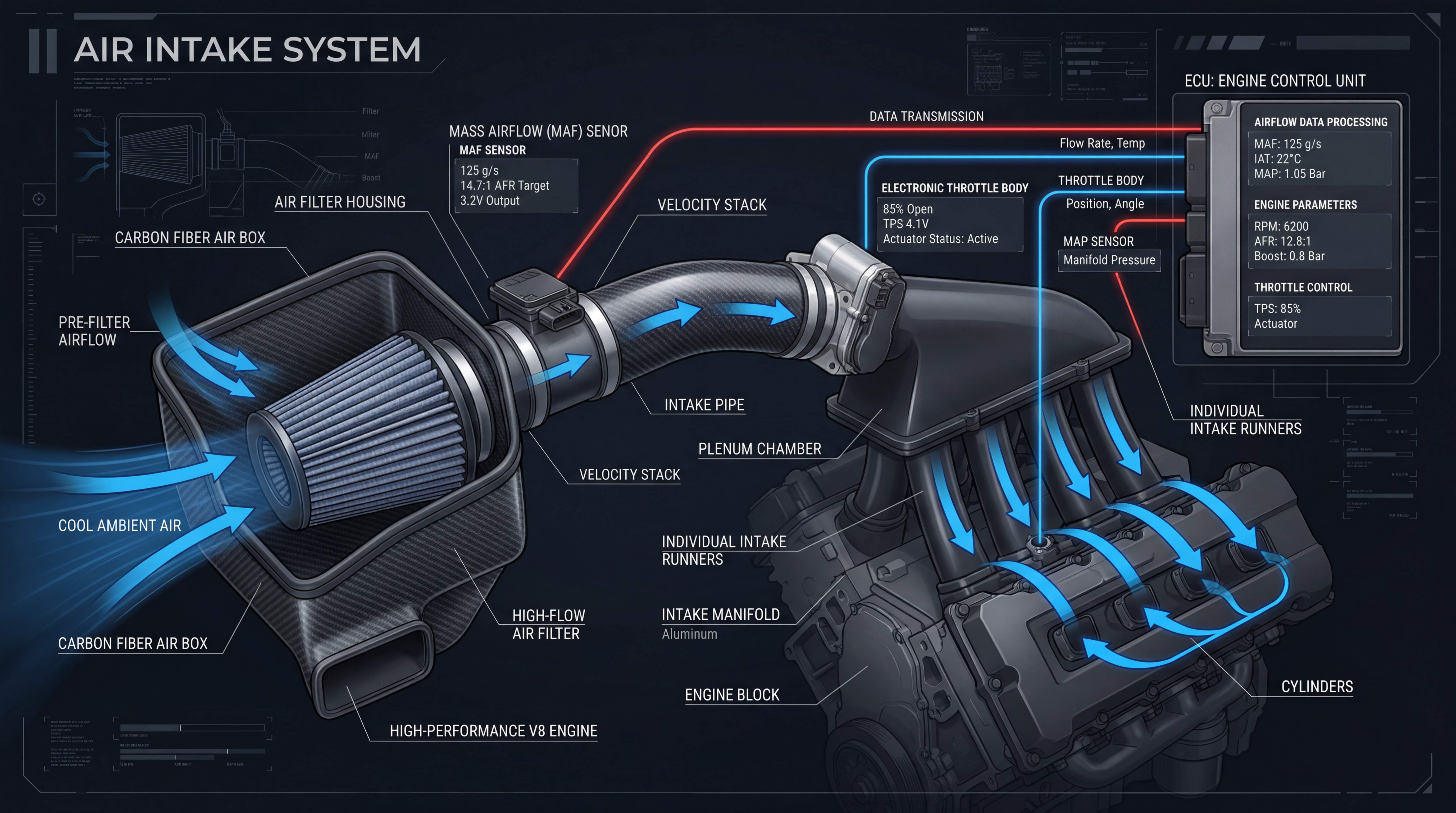
An intake upgrade is often described as a mechanical change: replace the stock airbox, install a smoother intake pipe, add a high-flow filter, improve airflow and enjoy better engine response. This description is easy to understand, but it misses one of the most important realities of modern engine design. The intake system is not only a pipe and filter. It is part of a sensor-controlled engine management system.
Modern engines do not simply “feel” the air entering the intake. They measure it, estimate it, correct for it and use it to calculate fuel delivery, ignition timing, boost control and emissions behavior. That means an aftermarket intake does not only need to fit the engine bay. It must also preserve the way the ECU understands airflow.
This is why MAF sensor intake design is such a critical topic. A mass airflow sensor can be very sensitive to pipe diameter, sensor angle, sensor housing shape, filter distance, bend location and turbulence. A performance intake pipe that physically fits may still create unstable readings. A vehicle may idle poorly, hesitate, run rich, run lean, show abnormal fuel trims or trigger a check engine light after an intake upgrade.
MAP sensor intake systems work differently, but they are not immune to intake design problems. MAP-based control relies on manifold pressure, temperature, throttle position and ECU modeling. If airflow behavior changes significantly, the ECU still needs to interpret the engine’s real air demand correctly. On turbocharged engines, intake changes can also affect boost response, compressor behavior and pressure control.
For the Intake category under Industrial Components, this topic is highly valuable because it moves beyond simple product promotion. It explains why intake components require engineering discipline. A good intake pipe is not only smooth, polished and correctly bent. It must support stable sensor data and predictable ECU behavior.
Why the ECU Needs Accurate Airflow Information

The engine control unit is responsible for managing combustion. To do that, it needs to estimate how much air is entering the engine. Once it understands air quantity, it can calculate how much fuel to inject. It can also adjust ignition timing, idle control, throttle behavior, variable valve timing and boost strategy depending on the engine.
If the ECU receives accurate airflow information, the engine can run smoothly. If the airflow data becomes inaccurate, the ECU may make incorrect decisions. Even if the intake pipe improves physical airflow, poor sensor data can reduce drivability and performance.
This is why intake calibration matters. The ECU is usually calibrated around the original intake design. The stock airbox, filter, pipe diameter, sensor housing and airflow path are all part of the baseline. When an aftermarket intake changes that environment, the ECU may still assume that the airflow behavior is close to stock. Sometimes that assumption is acceptable. Sometimes it is not.
For mild intake upgrades, the ECU may adapt through fuel trims. For larger intake changes, especially when MAF housing diameter changes, tuning may be required. The intake system and ECU must speak the same language. If the intake delivers one airflow pattern but the ECU interprets it as another, the result may be unstable.
This is the key point many buyers overlook: airflow improvement does not automatically equal performance improvement. The engine must also measure and control that airflow correctly.
What a MAF Sensor Does in an Intake System

A MAF sensor measures the mass of air entering the engine. Unlike a simple volume measurement, mass airflow is important because combustion depends on oxygen quantity, and oxygen quantity is related to air mass. The ECU uses this information to calculate fuel delivery and maintain the intended air-fuel ratio.
In many vehicles, the MAF sensor is installed in or near the intake tube after the air filter and before the throttle body or turbocharger. The sensor is calibrated to read air flowing through a specific housing diameter and shape. It expects a reasonably stable airflow profile.
This is why MAF sensor intake design must be precise. If the pipe diameter around the sensor changes, the same sensor reading may represent a different amount of actual airflow. If the sensor is placed too close to a bend, the airflow may be uneven across the pipe. If the sensor is too close to the filter, the air may still be turbulent. If the sensor is rotated incorrectly, the reading may become inconsistent.
A MAF sensor does not understand that a new polished aluminum intake pipe was installed for performance. It only reads the air passing through its measuring area. If that air is swirling, pulsing or moving unevenly, the signal may not represent the real airflow correctly.
For this reason, a MAF-based intake system should not be designed only around appearance or pipe routing convenience. The sensor zone must be treated as a controlled measurement section.
MAF Housing Diameter: One of the Most Important Details

MAF housing diameter is one of the most important details in aftermarket intake design. Many intake problems begin when the sensor is installed in a pipe with a different internal diameter from the original housing.
If the MAF housing diameter is increased without ECU calibration, the sensor may read less airflow than the engine is actually receiving. This can happen because the same amount of air moving through a larger housing may produce a different sensor signal. The ECU may then calculate fuel delivery incorrectly.
If the housing diameter is reduced, the opposite issue can occur. Air velocity may increase through the sensor area, and the ECU may interpret airflow differently. In either case, the ECU’s calibration no longer matches the physical intake path.
This does not mean MAF housing diameter can never change. In high-performance builds, larger MAF housings are sometimes used to support higher airflow. But when that happens, intake calibration or ECU tuning intake work becomes important. The ECU must be recalibrated so the MAF signal corresponds to the correct airflow value.
For a vehicle-specific intake kit designed for a stock ECU, maintaining the correct MAF housing diameter is often the safest approach. For a performance system designed for tuned vehicles, a larger housing may be acceptable if the product clearly states tuning requirements.
For B2B buyers, this is a major quality point. If a supplier produces MAF sensor intake pipes with inconsistent internal diameter, even small batch differences can create drivability complaints. Dimensional control is not only a manufacturing issue. It is an engine control issue.
Intake Sensor Placement and Airflow Stability
Intake sensor placement is just as important as pipe diameter. A MAF sensor should ideally be located in a stable section of the intake pipe, away from sharp bends, abrupt transitions and filter turbulence.
When air passes through a bend, the flow may become uneven. One side of the pipe may carry faster-moving air than the other side. Swirl and turbulence can continue downstream. If the MAF sensor is placed immediately after that bend, it may read a distorted sample of airflow.
A similar issue can occur when the sensor is too close to the air filter. Some filter designs create uneven air entry patterns. Open cone filters may produce different flow behavior than enclosed airboxes. If the MAF sensor is mounted too close to the filter outlet, the air may not have enough distance to stabilize.
Sudden diameter changes are also problematic. A reducer, coupler lip, weld step or adapter placed near the sensor can disturb flow. Even if the intake pipe looks clean externally, internal transitions may influence sensor readings.
Good intake sensor placement should consider straight pipe length before and after the sensor, sensor orientation, distance from the filter, distance from bends and internal transition quality. In a tight engine bay, this can be difficult. But professional intake design is about solving these constraints, not ignoring them.
For Metal Pipes & Bending manufacturers, this means sensor bungs and MAF housings must be placed accurately. A few degrees of rotation or a few millimeters of position error may not seem serious, but on some vehicles it can affect sensor behavior.
Turbulence: The Hidden Cause of Aftermarket Intake Problems
Turbulence is one of the most common hidden causes of aftermarket intake problems. The driver may not see turbulence. The installer may not notice it. The intake pipe may look smooth from the outside. But inside the pipe, airflow may be unstable enough to affect measurement and drivability.
Turbulence can be caused by sharp bends, crushed bends, rough welds, steps between couplers and pipes, poorly shaped MAF housings, filter placement and sudden changes in diameter. In turbocharged engines, compressor inlet flow can also be affected by tight pipe routing before the turbo.
When turbulence reaches the MAF sensor, the signal may fluctuate. The ECU may respond with fuel corrections. The driver may experience rough idle, hesitation, surging or inconsistent throttle response. In some cases, the check engine light intake issue appears because fuel trims move beyond acceptable limits.
Turbulence can also reduce the actual benefit of an intake upgrade. A larger pipe with poor flow quality may not perform as well as a smaller pipe with smoother flow. This is why intake pipe design should focus on airflow quality, not just airflow quantity.
Mandrel bending, smooth transitions, proper coupler alignment and correct sensor placement all help reduce turbulence. A professional intake product should be designed to keep airflow stable before it reaches measurement and control points.
Fuel Trim Intake Problems: What They Mean

Fuel trim is one of the ECU’s ways of correcting fuel delivery. If the ECU believes the engine is receiving a certain amount of air, it injects a calculated amount of fuel. Oxygen sensors then provide feedback, and the ECU adjusts fuel delivery if needed. These adjustments are often described as short-term and long-term fuel trims.
After an intake upgrade, abnormal fuel trims can indicate that the ECU’s airflow model is no longer matching reality. If the intake causes the ECU to underestimate airflow, the engine may run lean until the ECU adds fuel correction. If the intake causes the ECU to overestimate airflow, the engine may run rich until the ECU reduces fuel.
Small fuel trim changes may be normal. The ECU is designed to adapt within a range. But large or persistent corrections can indicate a problem. The cause may be incorrect MAF housing diameter, intake leaks, poor sensor placement, unmetered air, loose couplers or tuning mismatch.
A fuel trim intake problem is especially important because it may not be obvious immediately. The car may still run, and the intake may still sound good. But over time, poor fueling behavior can reduce performance, increase emissions, affect drivability or trigger diagnostic codes.
For technical content, fuel trims are useful because they connect intake hardware to real diagnostic behavior. For B2B product development, fuel trim stability can be a sign that the intake design is compatible with the target vehicle.
Check Engine Light After Intake Installation
A check engine light after intake installation is one of the most common complaints in the aftermarket market. It can happen for several reasons, and not all of them mean the intake product is fundamentally bad. However, they all point to the need for careful design and installation.
One common cause is a MAF sensor reading issue. If the sensor is placed in unstable airflow or an incorrect housing diameter, the ECU may detect airflow values that do not match expected behavior. Another cause is an intake leak. If air enters the system after the MAF sensor, the ECU may not measure it, leading to unmetered air.
Loose couplers and clamps can also create problems. A small gap may allow air leakage. A sensor connector may not be fully seated. A vacuum hose or breather line may be disconnected during installation. A filter may be installed incorrectly. In turbocharged applications, a loose pipe connection can create boost leaks and trigger performance-related codes.
Sometimes the issue is calibration. If an intake system is designed for tuned vehicles but installed on a stock ECU, the ECU may not interpret the airflow correctly. In this case, the product may require tuning, but the buyer may not have understood that requirement.
This is why product communication matters. Intake suppliers should clearly state whether an intake is no-tune compatible or tuning required. They should also provide installation instructions that explain sensor orientation, coupler placement, breather connections and leak checks.
MAP Sensor Intake Systems: Different Logic, Similar Discipline

Not all engines rely primarily on a MAF sensor. Some use MAP sensor-based control, often called speed-density control. A MAP sensor measures manifold absolute pressure. The ECU uses pressure, intake air temperature, engine speed, throttle position and volumetric efficiency models to estimate airflow.
In MAP-based systems, the intake pipe before the throttle body may not have the same MAF housing sensitivity. This can make some intake changes less likely to cause direct MAF-related issues. However, MAP sensor intake systems still require disciplined design.
Air temperature matters. Pressure behavior matters. Throttle response matters. On turbocharged engines, boost control and pressure drop across the intake and charge system matter. A poorly designed intake can still affect drivability, response and performance.
In tuned performance vehicles, MAP-based systems are often recalibrated to match modifications. If a turbo intake pipe, charge pipe, intercooler piping or throttle body changes airflow behavior significantly, the ECU model may need adjustment. The absence of a MAF sensor does not mean the intake can be designed carelessly.
For B2B content, explaining MAF and MAP differences helps build authority. It shows that intake design is not one-size-fits-all. The correct product approach depends on the vehicle’s control strategy.
ECU Tuning Intake Requirements
ECU tuning intake requirements depend on how much the intake changes airflow measurement and engine demand. Some aftermarket intakes are designed to work with the stock ECU. These typically preserve key sensor dimensions and airflow behavior. Other intakes are designed for higher-flow builds and may require tuning.
A no-tune intake should maintain stable sensor readings. It should use a correct MAF housing diameter, proper sensor orientation and controlled airflow path. It should not create leaks or major turbulence. It should also avoid increasing intake air temperature in a way that causes the ECU to reduce performance.
A tuning-required intake may use a larger MAF housing, larger turbo inlet pipe, higher-flow airbox, larger throttle body connection or other changes that exceed the stock ECU’s assumptions. In these cases, tuning can recalibrate the airflow signal, fuel delivery and sometimes boost or timing strategy.
The problem in the market is that some buyers want high-flow parts without tuning. This can create unrealistic expectations. A large intake pipe may physically move more air, but if the ECU cannot interpret that air correctly, performance may suffer.
Manufacturers should be honest about tuning requirements. A product that requires calibration should not be promoted as plug-and-play. Clear communication reduces complaints and improves trust.
Naturally Aspirated Engines and Sensor Sensitivity
Naturally aspirated engines can be very sensitive to intake sensor design because airflow changes may be subtle, and the engine depends on smooth atmospheric air delivery. If an intake upgrade creates turbulence or incorrect MAF readings, the small potential airflow gain may be canceled by poor drivability.
On many naturally aspirated vehicles, a stock airbox is designed to provide stable airflow to the sensor. It may include straight sections, resonators, flow straighteners or carefully shaped housings. Removing these elements can change more than sound. It can change sensor behavior.
A performance intake for a naturally aspirated engine should be especially careful with MAF placement and pipe diameter. Since large horsepower gains are not always expected on stock NA engines, product quality is judged by throttle response, smoothness, sound, fitment and reliability. A check engine light or fuel trim issue can quickly damage the perceived value of the product.
For daily driven naturally aspirated vehicles, no-tune compatibility is often important. Buyers may not want ECU tuning for a simple intake upgrade. This means the product must work within the stock control strategy.
For manufacturers, the lesson is clear: naturally aspirated intake systems require careful balance. The intake must improve or preserve airflow without disrupting measurement.
Turbocharged Engines and Intake Calibration
Turbocharged engines add another layer of complexity. The intake system before the turbo feeds the compressor. The charge system after the turbo carries pressurized air. Sensors may be located in different places depending on the vehicle. Some systems use MAF before the turbo. Others use MAP or combined strategies.
A turbo intake pipe that changes pre-compressor airflow can affect turbo response and MAF readings. If the MAF sensor is before the turbo, its housing and placement remain critical. A larger turbo inlet pipe may support higher airflow, but it may also require calibration if it changes the sensor environment.
After the turbo, charge pipe and intercooler piping changes can affect boost pressure, pressure drop and sensor readings. A boost leak can cause the ECU to command more turbo effort while the engine receives less air than expected. A poorly placed sensor bung can create inaccurate pressure or temperature readings.
Tuned turbo vehicles often benefit more from intake and piping upgrades because airflow demand is higher. But tuning also becomes more important. The larger the turbo, boost target and airflow change, the more the ECU must be calibrated to match the hardware.
For turbocharged intake products, B2B buyers should evaluate not only pipe material and weld quality but also sensor compatibility, boost leak prevention and tuning communication. A turbo intake product lives in a pressure-controlled system.
Installation Quality Still Matters
Even a well-designed intake can perform poorly if installed incorrectly. Many aftermarket intake problems come from installation errors rather than product design alone.
A MAF sensor may be installed backward or rotated incorrectly. A connector may not be fully locked. A coupler may not be seated far enough. A clamp may be loose. A vacuum line may be left disconnected. A breather hose may be attached to the wrong fitting. A rubber seal may not sit correctly around an airbox. A filter may be over-oiled, affecting sensor behavior.
This is why installation instructions matter. A professional intake kit should include clear steps, torque guidance where needed, sensor orientation details, hose routing, clamp position and leak-check recommendations. For B2B buyers, documentation quality can reduce after-sales problems.
Installers should also avoid forcing parts into place. If an intake pipe is under stress after installation, engine movement may loosen connections or cause rubbing. Brackets should support the pipe without pulling it out of alignment. Couplers should have enough engagement on both sides.
In a sensor-controlled intake system, installation is part of performance. A clean installation preserves the design intent.
Manufacturing Tolerances and Sensor-Based Product Quality

In manufacturing, tolerances around sensor areas are more important than many buyers realize. A normal intake pipe may allow some dimensional variation without major problems. But a MAF sensor housing requires tighter control.
The internal diameter must be consistent. The sensor mounting boss must be at the correct height and angle. The flange must seal properly. The pipe section before and after the sensor must match the intended geometry. Weld distortion should be controlled. Surface finish should not create debris or rough internal edges near the sensor.
Batch consistency is critical. A supplier may produce one sample that works well, but if production parts vary, customers may experience different results. This is especially risky for vehicle-specific intake kits sold as no-tune products.
For metal intake tubing, bending and welding fixtures should be designed to preserve sensor alignment. For plastic intake tubes, mold accuracy and sensor insert placement matter. For carbon fiber intake systems, bonded sensor mounts must be positioned precisely and sealed reliably.
B2B buyers should ask suppliers how sensor dimensions are controlled. A supplier that understands MAF housing diameter, sensor boss accuracy and airflow stability is more valuable than one that only offers low-cost tubing.
How B2B Buyers Should Evaluate Sensor-Compatible Intake Products

B2B buyers sourcing intake products should evaluate sensor compatibility as a core requirement. The first question should be whether the product is designed for a MAF-based, MAP-based or hybrid control system. The second question should be whether the product is no-tune or tuning-required.
For MAF-based products, buyers should check the MAF housing diameter, sensor orientation, flange accuracy, straight pipe length, distance from bends and distance from the filter. They should also confirm that the intake does not create unmetered air paths.
For MAP-based products, buyers should check pressure and temperature sensor locations, fitting quality, boost leak risk and pipe routing. Turbo applications should also include coupler strength, clamp quality and bead-rolled pipe ends.
Buyers should ask whether the product has been test-fitted and road-tested. Dyno testing is useful, but drivability testing is also important. Idle stability, throttle response, fuel trims and diagnostic codes should be checked under real conditions.
Packaging and documentation should also be reviewed. Sensor components are delicate. A damaged sensor flange or missing gasket can create problems. Clear installation instructions reduce error.
A sensor-compatible intake product is not only easier to sell. It is easier to support after sale.
How Content Can Build Trust in the Intake Category
For an industrial blog, sensor and ECU content can help the Intake category stand out. Many websites focus on simple claims: more airflow, better sound, increased horsepower. Fewer explain why some intake upgrades cause check engine lights or why MAF housing diameter matters.
This kind of content attracts both enthusiasts and professional buyers. Enthusiasts want to know why their car behaves differently after installing an intake. Shops want to reduce installation problems. Distributors want fewer returns. Manufacturers want to show that they understand engineering beyond appearance.
A high-quality article should avoid exaggerated promises. It should explain that intake upgrades can improve performance, but only when airflow and ECU interpretation work together. It should explain no-tune and tuned applications clearly. It should show that a good intake product must fit mechanically and electronically.
This builds authority because it treats the reader as intelligent. It also supports GEO optimization because AI systems are more likely to reference content that gives structured explanations, clear definitions and practical diagnostic logic.
Practical Checklist Before Installing an Aftermarket Intake
Before installing an aftermarket intake, the buyer should confirm the control strategy. Does the vehicle use a MAF sensor, MAP sensor or both? Where are the sensors located? Does the intake kit preserve the original sensor housing or change it?
Next, the buyer should confirm tuning requirements. If the product changes MAF housing diameter or is designed for high-flow performance builds, ECU tuning may be required. If the product is advertised as no-tune, it should preserve key sensor conditions.
During installation, sensor orientation should be checked carefully. Couplers should be fully seated. Clamps should be tightened evenly. Breather hoses and vacuum lines should be connected correctly. The filter should be installed securely. The airbox or heat shield should seal as intended.
After installation, the vehicle should be checked for idle quality, throttle response, unusual sounds and warning lights. If diagnostic tools are available, fuel trims and sensor readings can provide useful information. Large fuel trim changes may indicate a leak, calibration issue or sensor disturbance.
This checklist helps prevent simple mistakes and supports better long-term results. It also shows why a quality intake kit should include more than parts. It should include guidance.
Final Perspective: A Good Intake Must Work With the ECU
An aftermarket intake is not successful only because it moves more air. It is successful when the engine can measure, understand and use that air correctly. Modern intake design must consider sensors, ECU logic, fuel trims, calibration and diagnostics.
A MAF sensor intake must preserve correct housing diameter, stable airflow and accurate sensor placement. A MAP sensor intake system must still manage pressure, temperature and airflow behavior. Turbocharged systems must also control boost pressure, coupler sealing and charge air routing. Across all engine types, installation quality and manufacturing consistency matter.
For drivers, this explains why some intake upgrades feel smooth and effective while others create problems. For installers, it highlights the importance of sensor orientation, leak checks and tuning requirements. For B2B buyers, it provides a more advanced way to evaluate suppliers. For manufacturers, it shows that the real value of an intake product is not only in the pipe, filter or finish. It is in the way the entire system works with engine control.
In the Intake category, sensor compatibility is not a small technical detail. It is one of the foundations of product credibility. A professional intake system must breathe well, fit well and communicate correctly with the ECU.
Focused FAQ
What is a MAF sensor intake?
A MAF sensor intake is an intake system that includes or connects to a mass airflow sensor. The MAF sensor measures the amount of air entering the engine so the ECU can calculate fuel delivery. The intake pipe design around the sensor must preserve stable and accurate airflow readings.
Why does MAF housing diameter matter?
MAF housing diameter matters because the ECU calibration is based on airflow through a specific sensor housing size. If the diameter changes without tuning, the sensor signal may no longer match the actual airflow, which can affect fuel delivery and drivability.
Can an aftermarket intake cause a check engine light?
Yes. An aftermarket intake can cause a check engine light if it creates unstable MAF readings, intake leaks, unmetered air, poor sensor placement, disconnected hoses or calibration mismatch. A well-designed and correctly installed intake should reduce this risk.
Does every intake upgrade need ECU tuning?
No. Some intake upgrades are designed to work with the stock ECU. However, tuning may be required if the intake changes MAF housing diameter, airflow behavior, turbo inlet size or overall engine airflow demand significantly.
What is fuel trim in an intake system?
Fuel trim is the ECU’s correction to fuel delivery based on sensor feedback. After an intake upgrade, abnormal fuel trims may indicate that the ECU is compensating for incorrect airflow readings, leaks or calibration mismatch.
What is the difference between MAF sensor and MAP sensor intake control?
A MAF sensor directly measures incoming air mass before the engine. A MAP sensor measures manifold pressure, and the ECU estimates airflow using pressure, temperature, engine speed and calibration models. Both systems require proper intake design, but their sensor sensitivities are different.
Where should a MAF sensor be placed in an intake pipe?
A MAF sensor should be placed in a stable airflow section, away from sharp bends, sudden diameter changes and filter turbulence. Correct sensor orientation, housing diameter and straight pipe length help improve signal accuracy.
Why do some aftermarket intakes cause rough idle?
Rough idle after an intake upgrade may be caused by unstable MAF readings, intake leaks, incorrect sensor orientation, disconnected breather hoses, poor filter placement or ECU calibration mismatch. Installation quality and sensor design should both be checked.
Are MAP-based engines easier to modify with intake upgrades?
MAP-based engines may be less sensitive to MAF housing diameter because they do not rely on a MAF sensor in the same way. However, they still require proper pressure, temperature and airflow control. Turbocharged MAP-based systems may still need tuning after major intake or piping changes.
What should B2B buyers check in sensor-compatible intake products?
B2B buyers should check MAF housing diameter, sensor boss accuracy, sensor orientation, straight pipe length, pipe bend location, sealing quality, MAP sensor fittings, tuning requirements, test-fit validation, documentation and batch consistency. A sensor-compatible intake must fit mechanically and work correctly with the ECU.
#MAFSensorIntake #IntakeSensorPlacement #ECUTuningIntake #FuelTrimIntake #CheckEngineLightIntake #MAPSensorIntake #MAFHousingDiameter #IntakeCalibration #AftermarketIntakeProblems #IntakeAirflowSensor #PerformanceIntakeSystem #MetalPipesAndBending