Types of Hydraulic Valves Directional, Pressure, Flow, Check and Cartridge Valves Explained
Hydraulic Valve Types Are Not Just Product Categories
When people search for hydraulic valve types, they often expect a simple list: directional valves, pressure valves, flow valves, check valves, cartridge valves, solenoid valves and proportional valves. That list is useful, but it is only the beginning.
In real hydraulic systems, a valve type is not just a product name. It is a control decision.
A hydraulic valve determines how fluid power is used inside a machine. It may decide where the oil flows, how much pressure is allowed, how fast an actuator moves, whether a load can stay in position, or whether a circuit can protect itself when pressure rises unexpectedly. This means that hydraulic valves are not passive components. They directly shape machine behavior.
A loader arm that lifts smoothly, a press that builds pressure safely, a forklift mast that holds a load without drifting, and an agricultural implement that responds consistently all depend on the right valve logic. The pump provides flow, and the actuator produces movement, but the valve controls the meaning of that movement.
This is why hydraulic valve selection should never begin with appearance, port size or price alone. A valve must be selected based on function, pressure, flow, actuator behavior, safety requirements, control method and operating environment.
A directional control valve may look like the most important valve because it visibly changes actuator movement. But a pressure relief valve may be the component that prevents system damage. A flow control valve may determine whether movement feels smooth or unstable. A check valve hydraulic circuit may prevent reverse flow and protect position. A counterbalance valve may be the difference between controlled lowering and dangerous load drop. A hydraulic cartridge valve may allow all of these functions to fit into a compact manifold block.
The goal of this guide is not only to define valve names. The goal is to explain what each valve does inside real industrial and mobile hydraulic systems, why it matters, and how buyers, engineers and maintenance teams should think about choosing them.
Start With the Control Task, Not the Valve Name

A common mistake in hydraulic system design is asking, “What valve should I buy?” before asking, “What control task does the system need?”
A better starting point is to describe the machine action.
Does the actuator need to extend and retract?
Does the system need to limit maximum pressure?
Does the cylinder need to move slowly and predictably?
Does oil need to be blocked from flowing backward?
Does a suspended load need to remain secure?
Does the machine need electrical control from a switch, PLC or controller?
Does the movement need variable speed rather than simple on/off control?
Does the valve need to fit inside a compact manifold block?
Each question points to a different hydraulic valve family.
If the task is to change the direction of oil flow, the system likely needs a directional valve. If the task is to prevent excessive pressure, it needs a pressure control valve such as a relief valve. If the task is speed regulation, it may need a flow control valve. If reverse flow must be blocked, a check valve is used. If the system needs compact integration, cartridge valves may be preferred. If electrical actuation is needed, a solenoid hydraulic valve may be suitable. If the system requires variable and precise control, a proportional hydraulic valve may be the better solution.
This task-based view is important because the same machine may need several valve types working together. A hydraulic lift may use a directional valve to raise and lower, a relief valve to protect pressure, a flow control valve to regulate speed, a check valve to stop reverse flow, and a counterbalance valve to control load movement. These valves may be separate components or integrated into a hydraulic manifold.
In other words, the correct valve type depends on the control problem being solved. A good hydraulic system is not built from isolated parts. It is built from coordinated control functions.
Directional Control Valves: Controlling Where the Oil Goes

A directional control valve controls the path of hydraulic oil. It determines whether oil flows to one side of a cylinder, the other side of the cylinder, a hydraulic motor, a return line, or a blocked position. Because direction determines machine movement, directional valves are among the most recognizable and widely used hydraulic valve types.
In a cylinder circuit, a directional valve can extend the cylinder, retract it, stop it, or hold it in a neutral position. In a motor circuit, it can control rotation direction. In mobile equipment, directional valves are used for loader arms, attachments, steering functions, lifting systems and auxiliary tools. In industrial equipment, they are used in presses, clamps, transfer machines, test benches and production systems.
The most common directional valve descriptions include the number of ports and positions. For example, a 4/3-way directional valve has four ports and three spool positions. The ports may include pressure, tank and two actuator ports. The three positions may correspond to extend, neutral and retract, although the exact behavior depends on spool design.
The neutral position is especially important. Some directional valves allow pump flow to return to tank in neutral. Some block all ports. Some connect actuator ports to tank. Some maintain pressure in certain lines. These center conditions affect heat generation, load holding, pump unloading and actuator stability.
This is why replacing a directional valve only by matching size can be risky. Two valves may have similar port dimensions but completely different neutral behavior. One may be suitable for an open center circuit, while another may be designed for a closed center system. A wrong choice can cause overheating, actuator drift, poor response or pump stress.
Directional valves can be operated manually, mechanically, hydraulically, pneumatically or electrically. Manual directional valves are common in simple machines where an operator directly controls movement. Solenoid-operated directional valves are common where electrical control is needed. Pilot-operated directional valves are often used for larger flows, where direct actuation would require too much force.
From an industry perspective, directional valves are not just “movement valves.” They are the components that translate control intention into actuator direction. Their selection affects not only whether the machine moves, but how safely and predictably it moves.
Pressure Relief Valves: Protecting the System From Excessive Pressure

A pressure relief valve is one of the most important safety-related components in a hydraulic system. Its main function is to limit maximum pressure. When system pressure rises above a set value, the relief valve opens and diverts oil to tank or another low-pressure path. This prevents damage to pumps, hoses, actuators, seals, fittings and structural components.
Hydraulic systems can experience pressure rise for many reasons. A cylinder may reach the end of stroke. A load may be heavier than expected. A valve may close suddenly. A hose may be blocked. A mechanical jam may stop actuator movement. Without pressure protection, the pump may continue trying to force oil into a restricted circuit, causing dangerous pressure spikes.
The pressure relief valve acts as a controlled escape path.
However, a relief valve should not be treated as a normal operating valve in every condition. If a system continuously operates over the relief valve, energy is wasted as heat. This can cause oil temperature rise, reduced efficiency, seal damage and shorter component life. In a well-designed system, the relief valve protects against overload but should not be the main method of everyday flow control.
Relief valve setting is also critical. If the setting is too low, the machine may feel weak because the valve opens before the actuator can generate enough force. If the setting is too high, components may be exposed to unsafe pressure. If the relief valve is contaminated or stuck open, the system may fail to build pressure. If it is stuck closed, the system may lose protection.
There are different designs of pressure relief valves, including direct-acting and pilot-operated versions. Direct-acting relief valves are often simple and responsive, while pilot-operated relief valves may handle larger flows with better pressure stability. The correct choice depends on system pressure, flow rate, response requirements and machine function.
In many hydraulic manifold blocks, relief valves are integrated close to the pressure inlet or specific actuator circuits. This allows pressure protection to be compact and function-specific. For example, a manifold may include a main relief valve for the system and additional circuit relief valves for individual actuator lines.
The key industry point is clear: a pressure relief valve is not just a backup part. It defines the pressure boundary of the hydraulic system. If pressure control is wrong, the rest of the circuit cannot perform reliably.
Flow Control Valves: Controlling Speed and Movement Stability
A flow control valve regulates the amount of hydraulic oil passing through part of a circuit. Since actuator speed is related to flow rate, flow control valves are used to manage how fast cylinders extend, how quickly they retract, or how fast hydraulic motors rotate.
This makes flow control essential for machine behavior. Without proper flow control, a cylinder may move too fast, too slowly, or inconsistently under changing load conditions. In lifting equipment, uncontrolled speed can create safety risks. In industrial production equipment, unstable speed can affect process quality. In mobile machines, poor speed control can make operation feel rough or unpredictable.
There are several types of flow control methods. A simple needle valve can restrict flow through an adjustable orifice. A pressure-compensated flow control valve can maintain a more stable flow even when load pressure changes. Some circuits use meter-in control, where flow entering the actuator is controlled. Others use meter-out control, where flow leaving the actuator is controlled. The right method depends on load direction, actuator type and safety requirements.
Meter-out control is often important where gravity or external force may drive a cylinder. If a vertical load is being lowered, controlling the outlet flow can prevent the load from running away. However, for some circuits, meter-in control may be suitable when load conditions are stable and positive control is maintained.
Flow control valves also influence heat generation. Restricting flow creates pressure drop, and pressure drop creates heat. If flow is throttled unnecessarily or if a valve is undersized, the system may waste energy and overheat. Therefore, flow control must be designed carefully rather than added casually.
In modern systems, flow control may be handled by proportional valves, variable displacement pumps or electronic control strategies. But mechanical and adjustable flow control valves remain widely used because they are simple, reliable and cost-effective in many applications.
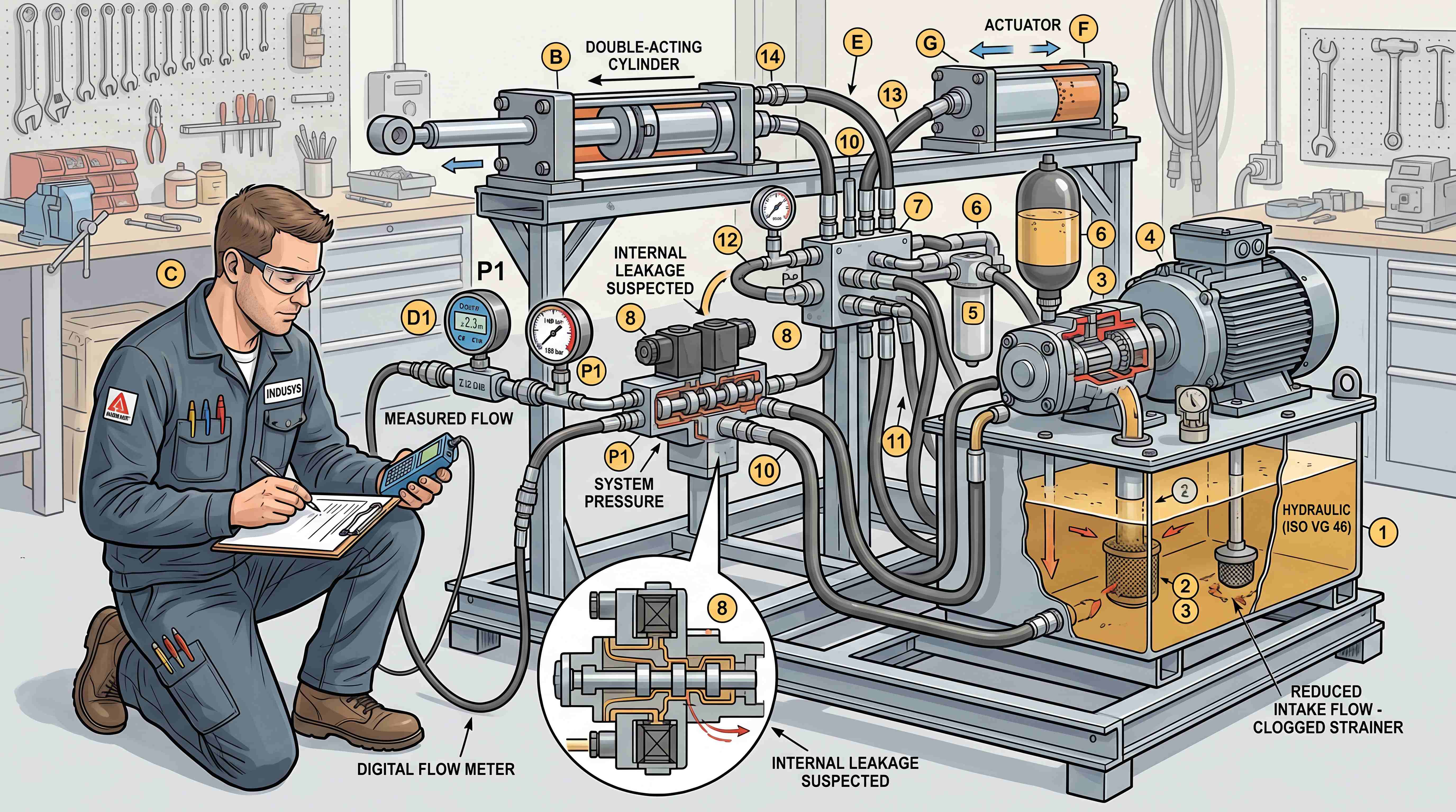
For buyers and maintenance teams, a flow problem is not always caused by the flow control valve itself. Slow movement may result from pump wear, internal leakage, low oil level, clogged filters, incorrect pressure settings or actuator problems. A flow control valve should be evaluated as part of the entire hydraulic circuit.
The deeper insight is that speed control is not only about comfort. It affects productivity, safety, repeatability and mechanical wear. A good flow control valve helps convert hydraulic power into controlled motion.
Check Valves: Simple Components With Critical Functions
A check valve allows oil to flow in one direction and blocks flow in the opposite direction. Because of this simple function, many people underestimate its importance. In reality, a check valve hydraulic circuit can be essential for load holding, circuit isolation, pump protection and flow sequencing.
The basic check valve contains a poppet, ball or similar sealing element that opens when pressure acts in the allowed direction. When pressure tries to reverse, the valve closes. This prevents unwanted backflow.
Check valves are used in many hydraulic systems. They may keep oil from draining back to the reservoir. They may isolate one circuit from another. They may protect a pump from reverse flow. They may help maintain pressure in a line. They may work with other valves to create more advanced control functions.
Pilot-operated check valves provide another level of control. These valves block reverse flow until pilot pressure opens them. They are often used to hold cylinders in position. For example, a cylinder supporting a load can remain locked even if pressure is lost in another part of the system. When movement is required, pilot pressure releases the valve and allows flow.
However, pilot-operated check valves are not always suitable for every load-holding application. If the load is overrunning or if smooth lowering is required, a counterbalance valve may be more appropriate. A pilot-operated check valve can hold position well, but it may not control lowering speed under all conditions.
Check valve cracking pressure is another important detail. Cracking pressure is the pressure required to open the valve. If it is too high, the valve may create unnecessary pressure drop. If it is too low, it may not provide the desired circuit behavior. Valve orientation, contamination resistance and sealing performance also matter.
In manifolds, check valves may appear as cartridge-style components installed into internal passages. This allows compact circuit design and reduces external plumbing.
The practical lesson is that check valves may be small, but they often protect the logic of the circuit. A failed or misapplied check valve can lead to drift, reverse flow, pressure loss or unexpected actuator movement.
Counterbalance Valves: Controlling Loads That Want to Move by Themselves
A counterbalance valve is used when a load may move under gravity or external force even when the pump is not actively driving it. This is common in lifting platforms, cranes, booms, dump bodies, vertical cylinders, winches and other load-holding applications.
The purpose of a counterbalance valve is not only to hold a load. It also helps control the movement of an overrunning load. When a cylinder lowers a heavy load, gravity may try to pull the load faster than the pump supplies oil. Without proper control, the actuator can run away, causing unstable movement or dangerous dropping.
A counterbalance valve creates back pressure and allows controlled lowering. It usually remains closed until pilot pressure signals that movement is intended. When the valve opens, it meters flow out of the actuator in a controlled way.
This makes counterbalance valves different from basic check valves. A check valve can block reverse flow, but it does not necessarily provide smooth control of a lowering load. A counterbalance valve is designed to manage load-induced movement.
Correct setting is critical. If the counterbalance setting is too high, the system may waste energy and generate heat. If the setting is too low, the load may not be held securely. Pilot ratio, load pressure, cylinder geometry and machine dynamics all influence valve selection.
Counterbalance valves are also important for hose failure protection. If a hose or line fails, the valve can help prevent uncontrolled descent when properly located and applied. In many safety-sensitive systems, load-holding valves are installed close to the actuator to reduce risk.
From an engineering standpoint, counterbalance valves are among the most important hydraulic valve types for safety. They are not optional accessories in applications where gravity can drive motion. They are part of the machine’s risk control strategy.
For SEO and content planning, counterbalance valve topics are valuable because they connect product selection with real user problems: drifting loads, unstable lowering, jerky boom movement, lift platform safety and cylinder holding issues.
Hydraulic Cartridge Valves: Compact Building Blocks for Manifold Systems
A hydraulic cartridge valve is a compact valve element designed to fit into a cavity, often inside a hydraulic manifold block. Cartridge valves can perform many functions, including pressure relief, flow control, check control, directional control and load holding.
The main advantage of cartridge valves is modularity. Instead of using separate inline valve bodies connected by hoses, designers can install multiple cartridge valves into a manifold block. The manifold provides internal passages, while the cartridge valves provide control functions. This creates a compact hydraulic integrated circuit.
Cartridge valves are widely used in mobile machinery, industrial equipment, agricultural machines, lifting systems and custom hydraulic power units. They are especially valuable where space is limited, leak points must be reduced, and repeated production is required.
There are different cartridge valve styles. Screw-in cartridge valves are common in compact manifold systems. Slip-in cartridge valves are often used in high-flow or high-performance industrial systems. The choice depends on pressure, flow, circuit function and design standards.
One of the biggest benefits of cartridge valves is flexibility. A manifold can be designed with cavities for several valve functions. If the system needs a different relief setting, flow control range or check function, the valve element may be changed while keeping the manifold concept similar. This supports modular design and product families.
However, cartridge valves require careful engineering. Cavity standards must match the valve. Flow capacity must be correct. Pressure drop must be considered. Seal compatibility matters. Contamination control is important because small internal passages and precise components can be sensitive to dirty oil.
Cartridge valves also require clear documentation. Maintenance teams need to know which cartridge performs which function, where it is installed, and what settings or replacement parts are required. A poorly labeled manifold can make troubleshooting difficult even if the design is technically sound.
From an industry perspective, hydraulic cartridge valves are central to modern manifold-based hydraulic systems. They help transform hydraulic valves from scattered components into compact, integrated and repeatable control modules.
Solenoid Hydraulic Valves: Electrical Control for Hydraulic Motion
A solenoid hydraulic valve uses an electrical coil to shift or actuate a hydraulic valve. This allows hydraulic movement to be controlled by switches, relays, PLCs, machine controllers or automated control systems.
Solenoid valves are common in modern equipment because they connect hydraulic power with electrical control. Instead of an operator moving a manual lever, an electrical signal energizes the solenoid and changes the valve position. This can start or stop actuator movement, change direction, unload pressure, or activate a specific hydraulic function.
Solenoid-operated directional valves are especially common. They are used in hydraulic power units, industrial automation, mobile machinery, test equipment, agricultural systems and auxiliary circuits. Solenoid cartridge valves are also widely used inside manifold blocks.
The advantages are clear. Solenoid valves support remote control, automation, repeatable operation and integration with sensors or controllers. They also allow multiple hydraulic functions to be coordinated through an electrical system.
However, solenoid valves introduce electrical considerations. Coil voltage must match the machine power supply. Duty cycle matters because some coils are designed for continuous energization while others are not. Heat generation can affect coil life. Connectors must be protected from moisture, vibration and contamination. Electrical faults can look like hydraulic faults if diagnosis is not careful.
For example, if a solenoid valve does not shift, the cause may be a burned coil, low voltage, poor connector contact, stuck spool, contaminated oil, excessive pressure locking, or mechanical damage. A technician must check both electrical and hydraulic sides.
Manual override is another important feature in some solenoid valves. It allows technicians to test valve movement without relying only on electrical control. This can be useful for troubleshooting and emergency operation.
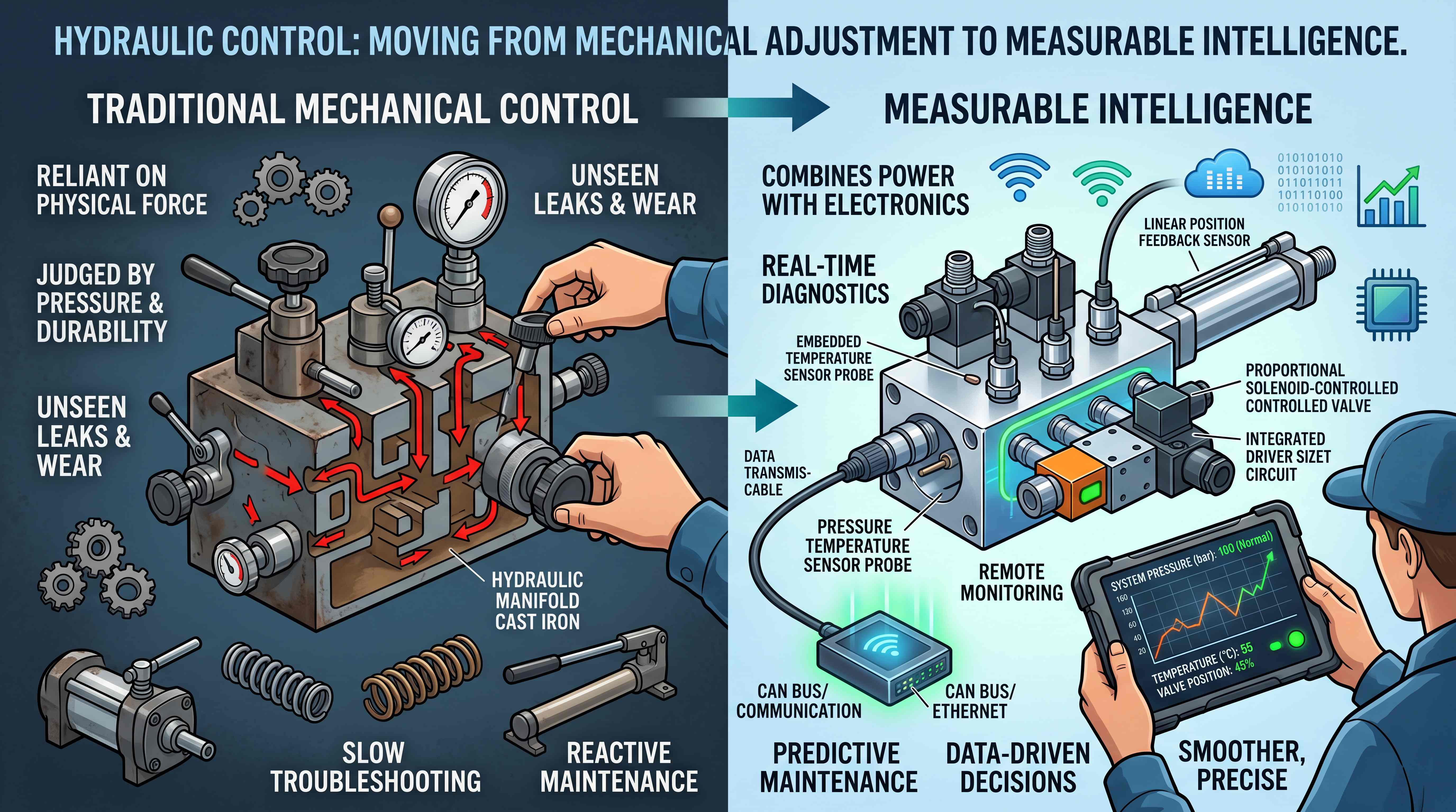
In more advanced equipment, solenoid valves may be controlled by machine software. The hydraulic circuit then becomes part of a larger mechatronic system. In this environment, valve response time, reliability and electrical diagnostics become more important.
The key point is that solenoid hydraulic valves are not simply electric versions of manual valves. They are the interface between hydraulic force and electronic control.
Proportional Hydraulic Valves: When On/Off Control Is Not Enough
A proportional hydraulic valve allows variable control of pressure, flow or direction based on an electrical input signal. Unlike a simple on/off solenoid valve, a proportional valve can adjust its opening gradually. This enables smoother movement, variable speed, controlled acceleration and more precise machine behavior.
Proportional valves are used when the machine needs more than basic extend and retract functions. They are common in mobile machinery, industrial automation, presses, simulation systems, steering circuits, material handling equipment and applications where controlled motion is important.
For example, a proportional directional valve can control both direction and flow to an actuator, allowing the cylinder to move slowly, quickly or anywhere in between. A proportional pressure valve can adjust pressure based on process requirements. A proportional flow valve can regulate actuator speed electronically.
The benefits include smoother operation, better controllability, programmable behavior and improved operator experience. In automated systems, proportional valves allow hydraulic motion to be coordinated with sensors, controllers and feedback loops.
However, proportional valves also require more careful system design. They may need electronic drivers or amplifiers. They may require proper signal calibration. Oil cleanliness is important because proportional components can be more sensitive than simple manual valves. Heat, pressure drop and response characteristics must also be considered.
A proportional valve should not be selected only because it sounds advanced. In some applications, a simple directional valve and mechanical flow control valve may be more reliable and cost-effective. Proportional control is valuable when the application truly requires variable and smooth control.
This is an important industry insight: not every hydraulic system needs the most advanced valve. The best valve is the one that matches the machine’s control requirement, maintenance capability and economic reality.
When used correctly, proportional valves can significantly improve machine performance. When used without proper understanding, they can increase cost and complexity without solving the real problem.
Manual, Mechanical, Pilot and Electric Actuation: How Valves Are Operated
Valve type describes what the valve does. Actuation method describes how the valve is operated. These two ideas should not be confused.
A directional valve may be manual, solenoid-operated, pilot-operated or mechanically actuated. A pressure valve may be direct-acting or pilot-operated. A flow control valve may be manually adjustable or electronically controlled. The actuation method affects usability, response, automation and maintenance.
Manual valves are simple and direct. An operator moves a lever or knob to control hydraulic function. They are common in agricultural machines, small hydraulic power units, service equipment and simple mobile applications. Their advantages include simplicity, low cost and easy understanding. Their limitations include less automation and dependence on operator skill.
Mechanical actuation uses physical movement from the machine to operate the valve. This may include cams, rollers or linkages. It can be useful for sequence control or position-based actions.
Pilot-operated valves use hydraulic pressure to shift or control a valve. This allows larger valves to be controlled with smaller pilot signals. Pilot control is common in high-flow systems and mobile hydraulic valve banks.
Electric actuation includes solenoid and proportional control. It supports automation, remote operation and electronic integration. This is increasingly important as hydraulic systems become more connected with machine control platforms.
The actuation method should match the machine’s operating model. A simple farm implement may not need electronic proportional control. A modern automated production line may require it. A high-flow industrial system may need pilot operation because direct solenoid force is not enough. A mobile machine may combine joystick commands, pilot hydraulics and electronic control.
When comparing hydraulic valve types, buyers should always ask two questions: What function does the valve perform? And how should that function be actuated?
Why One Machine Usually Needs Several Valve Types
A hydraulic machine rarely relies on only one type of valve. Most systems combine multiple valve functions to create safe and useful motion.
Consider a hydraulic lifting platform. It may need a directional control valve to raise and lower the platform. It may need a pressure relief valve to protect the system. It may need a flow control valve to control lowering speed. It may need a check valve or counterbalance valve to prevent uncontrolled descent. It may need a solenoid hydraulic valve for electric control. If the platform requires smooth acceleration or variable speed, it may need proportional control.
A construction machine attachment may also use several valve functions. The directional valve controls movement. Relief valves protect against overload. Flow controls adjust tool speed. Check valves isolate circuits. Counterbalance valves manage load holding. Cartridge valves may integrate all of these functions inside a compact manifold.
This combination is why hydraulic manifolds are so important. A manifold can organize several valve types into a single assembly. This reduces external hose complexity and makes the system more compact.
The real skill in hydraulic design is not knowing the name of every valve. It is knowing how valve functions interact. A relief valve setting can affect actuator force. A flow control valve can affect heat generation. A check valve can affect pressure trapping. A counterbalance valve can affect lowering smoothness. A directional valve center condition can affect pump unloading.
Poor interaction between valve functions can create problems even when each individual component is high quality. Good hydraulic system design depends on coordination.
Practical Hydraulic Valve Selection: What to Check Before Buying
Good hydraulic valve selection begins with system requirements. Buyers should not select valves only from a product photo or a rough match to an old part.
The first factor is pressure rating. The valve must be suitable for the maximum working pressure and pressure spikes expected in the system. Safety margin matters, especially in mobile or shock-loaded equipment.
The second factor is flow capacity. If the valve is too small for the required flow, it can create pressure drop, heat and poor actuator performance. If it is unnecessarily oversized, it may increase cost and reduce controllability.
The third factor is circuit function. The buyer must understand whether the valve is controlling direction, pressure, flow, reverse flow, load holding or proportional motion. Confusing one function with another can create dangerous results.
The fourth factor is actuator type. Cylinders and motors have different control needs. Vertical cylinders, rotary actuators and overrunning loads require special attention.
The fifth factor is control method. Manual, solenoid, pilot and proportional control each fit different operating models. The power supply, control signal and duty cycle must be considered for electric valves.
The sixth factor is fluid cleanliness. Some valves are more tolerant of contamination than others. Filtration, oil maintenance and environmental conditions affect valve life.
The seventh factor is installation format. Inline valves, subplate-mounted valves, stack valves and cartridge valves all require different mounting approaches. If the system uses a manifold block, cavity compatibility and port layout are critical.
The eighth factor is serviceability. A valve should be accessible, identifiable and replaceable. In complex systems, test ports and documentation can save significant maintenance time.
The ninth factor is application environment. Temperature, vibration, moisture, dust, corrosion and duty cycle can all affect valve performance.
The final factor is total lifecycle cost. A cheaper valve may cost more if it causes downtime, leakage, instability or frequent replacement. A more integrated solution may cost more upfront but reduce assembly time and leak points.
A professional approach to valve selection connects technical specifications with machine behavior.
Common Mistakes When Comparing Hydraulic Valve Types
One common mistake is choosing a valve based only on pressure rating. Pressure rating is essential, but it does not confirm that the valve has the right flow capacity, spool function, actuation method or control behavior.
Another mistake is replacing a directional valve without checking center condition. The neutral position can dramatically affect the circuit. A wrong center condition may cause overheating, pressure trapping, actuator drift or pump loading.
A third mistake is using a relief valve as a normal flow control method. If oil constantly passes over the relief valve during normal operation, the system wastes energy and generates heat.
A fourth mistake is using a simple check valve where a counterbalance valve is required. A check valve can block reverse flow, but it may not control an overrunning load safely.
A fifth mistake is choosing proportional valves when the application does not need proportional control. Advanced components should solve a real control problem, not simply add complexity.
A sixth mistake is ignoring contamination. Many valve failures are related to dirty oil, particles, varnish, water or poor filtration. If contamination is not controlled, even good valves may fail early.
A seventh mistake is treating hydraulic cartridge valves as universal inserts. Cartridge valves must match cavity standards, pressure, flow, seal materials and circuit function.
An eighth mistake is ignoring manifold layout. Even correct valves can perform poorly if internal passages are too restrictive or service access is poor.
These mistakes show why hydraulic valve types should be understood as part of system design, not as isolated catalog items.
Conclusion: The Right Valve Type Depends on the Machine’s Control Logic
Hydraulic valves are often described by category, but their real purpose is control.
A directional control valve controls where the oil goes. A pressure relief valve limits system pressure. A flow control valve regulates actuator speed. A check valve blocks reverse flow. A counterbalance valve controls loads that want to move by themselves. A hydraulic cartridge valve allows compact manifold integration. A solenoid hydraulic valve connects hydraulic motion to electrical control. A proportional hydraulic valve enables smoother and variable control.
Each valve type solves a different problem. In real machines, several valve types usually work together. Their interaction determines whether the hydraulic system is safe, efficient, responsive and easy to maintain.
For buyers, engineers and maintenance teams, the best way to understand hydraulic valve types is to start from machine behavior. What movement is required? What pressure must be controlled? What speed is acceptable? What load must be held? What level of automation is needed? What environment will the valve operate in?
The answer to these questions leads to better valve selection.
In the end, hydraulic valves are not just components in a parts list. They are the logic elements of a fluid power system. When selected and integrated correctly, they turn hydraulic pressure and flow into controlled, productive and reliable machine motion.
#DirectionalControlValve
#PressureReliefValve
#FlowControlValve
#CheckValveHydraulic
#HydraulicCartridgeValve
#SolenoidHydraulicValve
#ProportionalHydraulicValve
#CounterbalanceValve
#HydraulicValveSelection
#IndustrialHydraulics
#MobileHydraulics
#FluidPower
#HydraulicSystemDesign
#IndustrialComponents