Smart Hydraulic Valves and Sensor-Ready Manifolds The Next Step in Hydraulic Control
Hydraulic Control Is Moving From Mechanical Adjustment to Measurable Intelligence
Hydraulic systems were traditionally judged by force, pressure and durability. A good hydraulic circuit lifted heavy loads, pushed hard, survived harsh conditions and delivered reliable motion through pumps, valves, cylinders, hoses and manifolds. For many decades, that was enough. If a valve shifted correctly, if a relief valve protected the circuit, if a cylinder moved at the expected speed and if the machine did not leak, the hydraulic system was considered successful.
But modern machines are changing. Equipment is becoming more automated, more connected and more dependent on data. Operators expect smoother control. OEMs need repeatable performance across machine platforms. Maintenance teams want earlier warning before failure. Fleet managers want fewer unexpected breakdowns. Engineers want to understand not only whether a machine moves, but why it moves the way it does.
This is where smart hydraulic valves and the sensor ready hydraulic manifold become important.
The future of hydraulic control is not about replacing hydraulics with electronics. It is about combining hydraulic power with electronic intelligence. A hydraulic system still provides high force density, ruggedness and compact power transmission. But when hydraulic valves are combined with sensors, electronic control, diagnostic feedback and communication interfaces, the system becomes more measurable and more controllable.
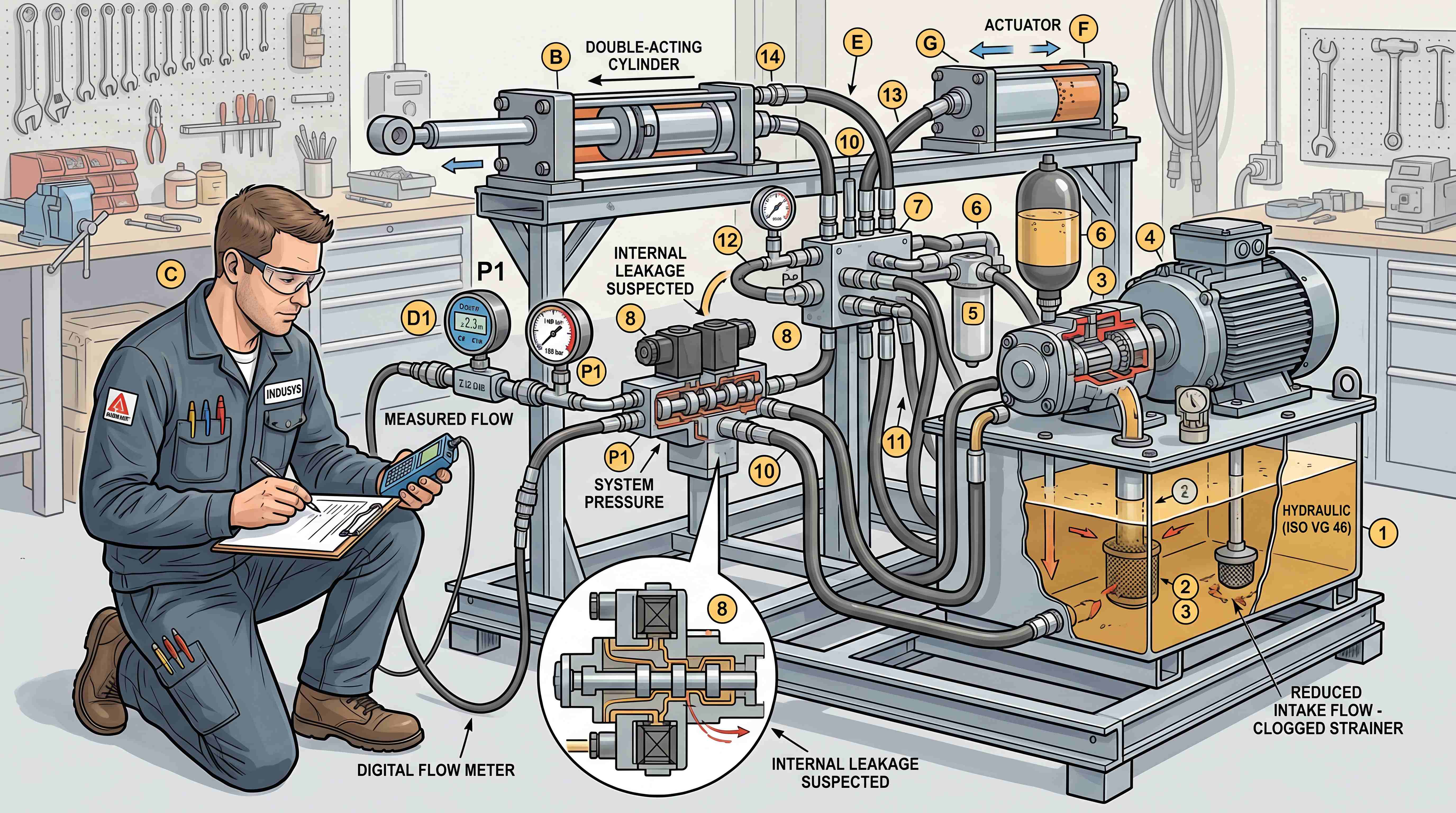
In older systems, many problems were invisible until they became serious. A valve began sticking, but nobody knew until the actuator moved erratically. A relief valve started leaking internally, but nobody noticed until the machine became weak. Oil temperature increased gradually, but the warning came late. Pressure spikes occurred during operation, but they were not recorded. A manifold passage became restricted, but the technician had to guess where the pressure drop occurred.
A smarter hydraulic system changes this relationship. With a hydraulic pressure sensor, temperature sensor, position feedback, proportional valve control and hydraulic manifold monitoring, the hydraulic circuit becomes easier to understand. The system can measure pressure, detect abnormal behavior, support diagnostics and communicate with the machine controller.
This does not mean every hydraulic system needs advanced electronics. A simple manual circuit may still be the best solution for a simple machine. But for mobile machinery, automation equipment, industrial presses, lifting platforms, agricultural machinery, energy equipment and OEM machine platforms, electro-hydraulic integration is becoming a serious design direction.
The industry is moving from “hydraulics that work” toward “hydraulics that can be controlled, measured and diagnosed.”
Why Smart Hydraulic Valves Are Becoming More Important

The rise of smart hydraulic valves is connected to several industry pressures.
The first pressure is automation. More machines now use electronic controllers, sensors and software logic. Hydraulic motion is no longer controlled only by a lever or simple solenoid. Machines may need automatic positioning, load control, speed adjustment, pressure modulation, safety interlocks and remote monitoring. This requires valves that can respond to electronic commands with predictable behavior.
The second pressure is performance. Manual valves and basic on/off solenoid valves are useful, but they often cannot provide smooth acceleration, controlled deceleration or variable motion. A proportional hydraulic valve can adjust flow or pressure according to an electrical signal, allowing smoother and more precise control.
The third pressure is reliability. In many machines, downtime is expensive. If a valve problem can be detected early through hydraulic valve diagnostics, maintenance can be planned before a failure stops production or disables equipment in the field.
The fourth pressure is energy efficiency. Hydraulics can waste energy when pumps run continuously, when flow is throttled unnecessarily or when pressure is higher than needed. Electronic control and sensor feedback can help match hydraulic output to real demand.
The fifth pressure is product standardization. OEM manufacturers want repeatable performance across machine batches. A sensor-integrated manifold or electronically controlled valve can help reduce variation caused by manual adjustment, inconsistent assembly or field tuning.
The sixth pressure is service complexity. Modern hydraulic systems are compact and integrated. A manifold may contain many cartridge valves, sensors, plugs, pilot passages and electrical connectors. Without monitoring and documentation, troubleshooting becomes difficult. Smart components can make compact systems easier to support.
The value of smart hydraulic control is not only high-tech branding. It addresses real machine problems: smoother motion, better control, reduced troubleshooting time, lower downtime risk and more repeatable performance.
Electro-Hydraulic Control Connects Oil Power With Electronic Logic

Electro hydraulic control means using electrical signals to control hydraulic power. The concept can be simple or advanced.
At the basic level, a solenoid valve is an electro-hydraulic component. An electrical signal energizes a coil, the valve shifts and hydraulic oil moves to an actuator. This is common in many industrial and mobile systems.
At a more advanced level, proportional valves, servo valves, pressure sensors, position sensors and electronic controllers work together. The controller sends commands to valves, reads sensor feedback and adjusts output according to machine logic. This allows variable speed, pressure control, position control and load-responsive behavior.
For example, a lifting platform may use sensors to detect cylinder pressure and position. The controller may command a proportional valve to raise or lower the platform smoothly. If pressure rises too quickly, the system may slow the movement. If a load imbalance is detected, the machine may stop or alert the operator.
In an industrial press, electro-hydraulic control may manage approach speed, pressing force, dwell pressure, decompression and return stroke. A basic valve circuit can move a press, but an electronic control system can make the process more repeatable and measurable.
In mobile machinery, electro-hydraulic control can support joystick operation, automated functions, load sensing, steering assistance, attachment control and safety logic. The hydraulic system still delivers force, but electronics define how that force is applied.
The key advantage is controllability. Hydraulic power is strong, but without proper control it can be rough, inefficient or difficult to diagnose. Electronic logic allows hydraulic valves to respond according to machine conditions rather than only operator input.
However, electro-hydraulic systems require careful design. Electrical signals must be reliable. Sensors must be placed correctly. Valves must match the control strategy. Wiring must survive vibration and moisture. Software must be tested. Hydraulic cleanliness must be maintained because proportional valves are often more sensitive than simple valves.
Electro-hydraulic control is powerful, but it is not magic. It works best when hydraulic design and electronic design are developed together.
Proportional Hydraulic Valves Make Motion Adjustable Instead of Only On or Off

A proportional hydraulic valve is one of the most important components in smart hydraulic control. Unlike a basic on/off valve, a proportional valve can vary flow or pressure according to an electrical input. This means the machine can move with different speeds, different force levels or smoother transitions.
In a simple solenoid valve system, the valve is usually open or closed. The actuator may start suddenly and stop suddenly. For many rugged applications, that is acceptable. But in systems that require smooth motion, precise positioning or controlled force, on/off control can be too rough.
A proportional directional valve can control actuator speed and direction. A proportional pressure valve can regulate pressure according to command. A proportional flow valve can adjust flow rate based on demand. These capabilities allow machines to perform more smoothly and more intelligently.
Common applications include injection molding machines, presses, lifting systems, agricultural equipment, construction machinery, test benches, material handling equipment and automation systems.
The benefits are clear. A proportional valve can reduce shock, improve operator feel, protect mechanical structures, support automated motion profiles and allow one machine platform to support different operating modes.
But proportional valves also require more support than simple valves. They may need electronic drivers, command signals, feedback loops, calibration, proper filtration and stable electrical power. They may be more sensitive to contamination because internal clearances and control edges are precise.
This is why proportional valve selection should not be treated as simply upgrading a standard valve. The whole circuit must be considered. Is the pump suitable? Is the flow range correct? Is the pressure drop acceptable? Is the oil clean enough? Does the controller provide the right signal? Does the operator need manual override? Is fail-safe behavior defined?
A proportional hydraulic valve helps turn hydraulic motion from rough action into controlled motion. But it must be integrated into a complete intelligent hydraulic system.
Sensor-Ready Manifolds Turn Hydraulic Blocks Into Data Points
A traditional manifold organizes oil passages and valve functions. A sensor ready hydraulic manifold goes one step further. It is designed not only to route oil, but also to measure what is happening inside the circuit.
A hydraulic manifold with sensors may include pressure sensor ports, temperature sensor ports, flow sensor positions, load-sense signal ports, diagnostic gauge ports, contamination monitoring interfaces or electrical connector integration. These features allow the manifold to become a measurement point inside the hydraulic system.
This is important because many hydraulic problems happen inside the circuit where they cannot be seen. Pressure may be normal at the pump but abnormal at the actuator. Return pressure may be higher than expected. A pilot line may fail to build pressure. A relief valve may open too early. A filter may restrict flow. A counterbalance valve may cause unstable motion. Without measurement points, technicians must guess.
A sensor-ready manifold improves visibility.
For example, pressure sensors can be placed at pump inlet, main pressure line, actuator ports, pilot lines and load-sense lines. Temperature sensors can identify heat problems. Flow sensors can help detect internal leakage or restriction. Diagnostic ports can allow manual measurement during service.
For OEMs, sensor-ready manifold design creates platform value. The same manifold concept may support basic machines with gauge ports and advanced machines with electronic sensors. This gives manufacturers flexibility. They can offer different machine versions without redesigning the entire hydraulic architecture.
Sensor-ready design also supports remote monitoring. If the hydraulic system is connected to a machine controller, pressure and temperature data can be logged. This can support preventive maintenance, warranty analysis and field troubleshooting.
However, sensor placement must be meaningful. Adding random sensors does not make a system smart. A sensor must answer a useful question. What pressure matters? Where does pressure drop occur? Which actuator needs monitoring? Which failure mode should be detected? What data will the controller use?
A sensor-ready manifold is valuable when sensor locations reflect real hydraulic logic.
Hydraulic Pressure Sensors Help Reveal What the Circuit Is Doing
The hydraulic pressure sensor is often the first sensor added to a smart hydraulic system because pressure is central to hydraulic performance. Pressure tells us about load, restriction, relief behavior, actuator force, pump condition and circuit status.
In a simple system, technicians may connect a pressure gauge only during service. In a smarter system, pressure sensors can provide continuous feedback to the controller. This allows the machine to respond to changing conditions.
For example, a pressure sensor on a cylinder port can help estimate load. A pressure sensor near the pump can detect whether the system is building pressure correctly. A sensor across a filter can help detect clogging. A sensor at a pilot line can confirm whether a pilot-operated valve is receiving the signal it needs. A sensor at a load-sense line can help diagnose pump control problems.
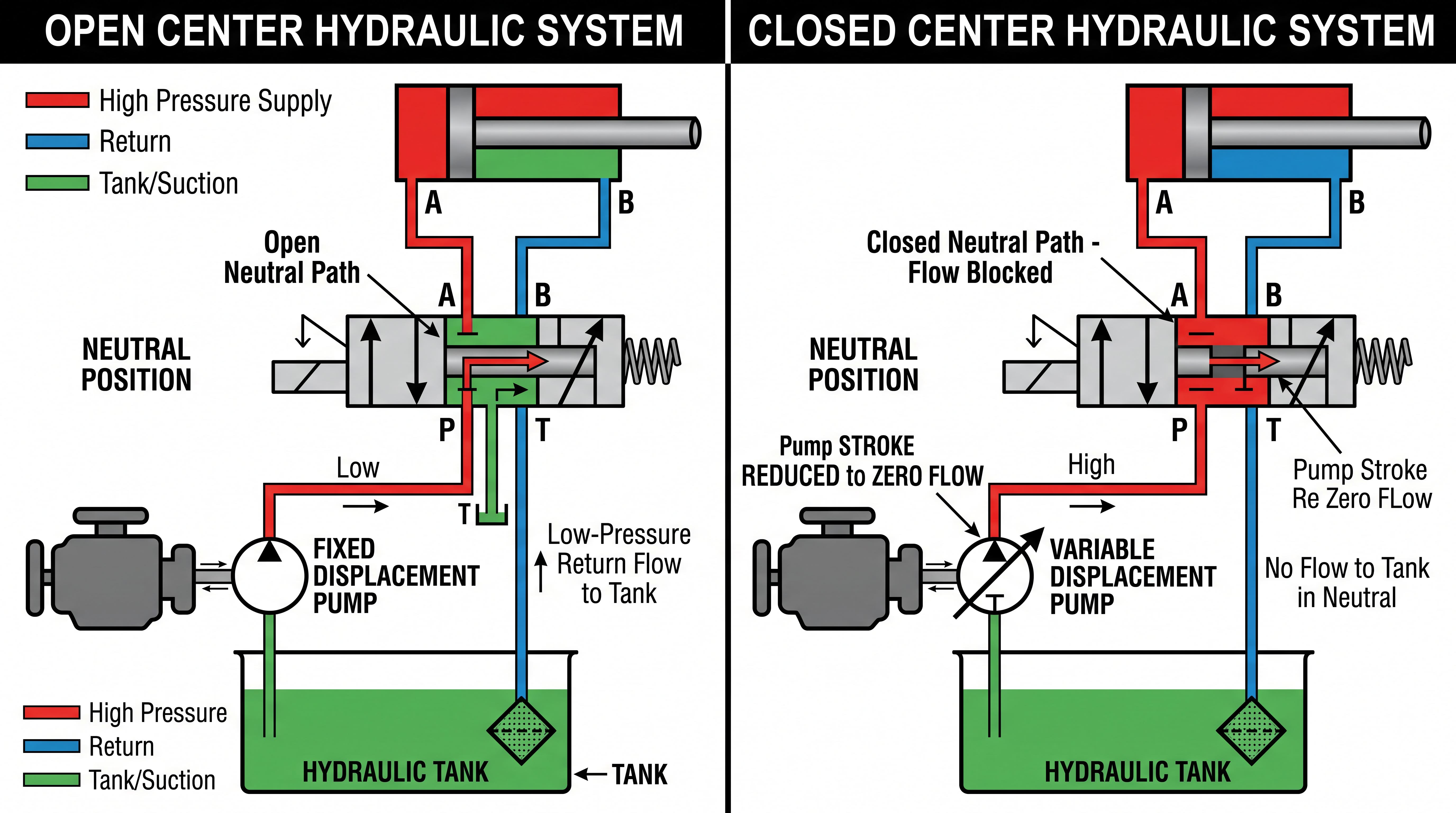
Pressure data can also help detect abnormal events. If pressure rises too fast, the system may be experiencing shock load or blocked movement. If pressure fails to rise, the issue may be internal leakage, relief valve failure or pump wear. If pressure remains high in neutral, the pump may not be unloading correctly. If pressure oscillates, the system may have instability, air, control loop issues or valve hunting.
But pressure sensors must be selected and installed correctly. Pressure range, overload capacity, accuracy, response time, fluid compatibility, connector protection and vibration resistance all matter. A sensor installed in the wrong location may produce data that looks useful but does not reflect the real problem.
Pressure sensing is powerful because it converts hidden hydraulic behavior into measurable information. It is one of the foundations of hydraulic manifold monitoring.
CAN Bus Hydraulic Valve Integration and Machine Communication
A CAN bus hydraulic valve or CAN-controlled valve module represents another step in electro-hydraulic integration. Instead of controlling each valve with simple individual wires only, the machine controller can communicate with valve electronics through a network.
This is common in modern mobile machinery, agricultural equipment and industrial automation systems. CAN communication can reduce wiring complexity, support diagnostics and allow more advanced control.
A valve module with communication capability may receive command signals, report status, provide fault codes, support calibration and communicate sensor data. This can help the machine controller understand whether a valve is responding correctly.
For example, a CAN bus valve system may report coil faults, supply voltage problems, communication errors, command deviations or sensor feedback issues. This can reduce troubleshooting time compared with traditional systems where technicians must manually test each wire and valve.
CAN bus integration can also support machine configurability. Different attachments, operating modes or regional versions may use the same hardware platform with different software settings. This is valuable for OEMs that build machine families.
However, CAN bus hydraulic valve systems require stronger system engineering. Network communication must be stable. Connectors must be protected. Electrical noise must be controlled. Diagnostics must be meaningful. Technicians must understand both hydraulic circuits and electronic communication.
A smart valve network should not make service harder. It should make faults easier to identify. Good documentation, diagnostic tools and training are essential.
The core value of CAN integration is not simply fewer wires. It is the ability to connect hydraulic control to the larger machine intelligence platform.
Hydraulic Valve Diagnostics Reduce Guesswork
Hydraulic valve diagnostics are valuable because hydraulic failures are often difficult to see directly. A valve may stick internally. A coil may be weak. A cartridge seal may leak. A pressure relief valve may open too early. A proportional valve may not reach commanded position. Without diagnostic information, technicians may replace parts randomly.
Smart diagnostics can include electrical diagnostics, pressure diagnostics, temperature monitoring, valve command feedback, actuator response monitoring and fault history.
Electrical diagnostics may detect open coil circuits, short circuits, low voltage, overcurrent or connector problems. Pressure diagnostics may compare expected pressure with measured pressure. Temperature diagnostics may detect overheating. Valve command diagnostics may compare commanded output with actual response. Runtime data may show whether a fault occurs only under certain loads or temperatures.
This can change maintenance from reactive repair to evidence-based troubleshooting.
For example, if a machine reports low pressure at an actuator port but normal pump pressure, the technician can focus on the valve, manifold passage or actuator circuit rather than replacing the pump. If a solenoid fault is reported, the technician can inspect the coil and wiring before opening the hydraulic system. If a pressure spike occurs repeatedly during a certain function, the OEM can adjust the control profile or improve circuit protection.
Diagnostics also help warranty analysis. Instead of relying only on operator descriptions, the manufacturer can review data. Did the system experience overpressure? Did the oil temperature exceed limits? Was the valve commanded correctly? Did pressure fail to build? This improves technical support.
Hydraulic diagnostics are most useful when they are tied to real troubleshooting logic. Too many alarms can confuse users. Meaningful diagnostic design should identify likely causes and guide the next inspection step.
Hydraulic Manifold Monitoring Supports Predictive Maintenance
Hydraulic manifold monitoring means using sensors and data to observe manifold circuit behavior over time. This can support predictive maintenance, especially in machines where downtime is expensive.
Monitoring may track pressure trends, temperature trends, filter restriction, valve response time, actuator speed, cycle count, load patterns and abnormal pressure spikes. Over time, this data can reveal degradation.
For example, if actuator pressure gradually increases for the same movement, friction may be increasing. If return pressure rises, a filter or return path may be restricted. If a cylinder requires more flow to maintain speed, internal leakage may be developing. If pressure spikes become more frequent, a valve may be closing too quickly or a load condition may have changed.
Predictive maintenance does not mean predicting every failure perfectly. It means detecting patterns earlier than traditional maintenance. The goal is to avoid surprise downtime and plan service at the right time.
A sensor-ready manifold helps because it provides stable measurement locations. Instead of adding temporary gauges after a failure, the system is designed from the beginning to collect useful information.
For OEMs, manifold monitoring can also improve future product design. Field data can reveal which functions experience the highest pressure, which circuits run hot, which valves are most stressed and which duty cycles are common. This feedback helps engineers improve the next generation of machines.
For end users, monitoring can reduce downtime and maintenance uncertainty. Instead of waiting for a machine to fail, maintenance teams can respond to trends.
The important point is that monitoring must be practical. Data should be easy to interpret. Alerts should be meaningful. Sensors should survive the environment. The system should support maintenance decisions, not create unnecessary complexity.
Smart Hydraulic Systems Still Depend on Good Basic Hydraulics
An intelligent hydraulic system still depends on the fundamentals of good hydraulic design. Smart sensors and electronic control cannot compensate for poor fluid cleanliness, wrong valve selection, undersized passages, weak manifold machining or incorrect circuit logic.
If oil is contaminated, proportional valves may stick. If a manifold passage is too small, pressure drop and heat will still occur. If a relief valve is set incorrectly, pressure protection is still wrong. If a sensor is installed at the wrong point, the data may mislead the controller. If wiring is poorly protected, the electronic control system may fail in the field.
This is why smart hydraulics should be built on strong hydraulic fundamentals.
The hydraulic circuit must be correct. The valve functions must match the machine task. The manifold must be machined accurately. The system must be cleaned. Filtration must be suitable. Hoses and fittings must be routed properly. Sensors must be placed where they can measure useful conditions. Electronic logic must match hydraulic behavior.
A common mistake is adding sensors only for marketing. A machine may claim to have smart hydraulics, but if the data is not used for control, diagnostics or maintenance, the value is limited. Smart design begins with a question: what decision will this data support?
Another mistake is making the system too complex for the service environment. If field technicians do not have diagnostic tools, documentation or training, advanced electronics may become a service burden. A good smart hydraulic system should be easier to diagnose, not harder.
The best intelligent systems combine robust hydraulic architecture with practical electronic insight.
How OEMs Can Use Smart Manifold Design Strategically
For OEM manufacturers, smart manifold design can become part of product strategy. A hydraulic manifold with sensors is not only a component. It can become a standardized control module across a machine platform.
This has several advantages.
First, it improves repeatability. If every machine uses the same tested manifold module, performance variation is reduced.
Second, it supports product tiers. A basic machine may use the same manifold with mechanical gauge ports. A premium machine may use electronic sensors and controller integration. This allows flexible product positioning.
Third, it improves service support. A standardized sensor-ready manifold can provide consistent diagnostic points. Service manuals and training become easier.
Fourth, it supports remote service. If machine data can be accessed by service teams, troubleshooting can begin before a technician arrives on site.
Fifth, it supports lifecycle learning. OEMs can study real operating data and improve future machines.
However, OEMs should avoid over-customization without purpose. A smart manifold should still use practical valves, accessible sensors, standard connectors where possible and clear documentation. Overly unique components may increase supply chain risk and service cost.
Good OEM smart manifold strategy balances integration, standardization and serviceability.
Design Questions Before Building a Sensor-Ready Hydraulic Manifold
Before designing a sensor-ready hydraulic manifold, engineers should answer several practical questions.
Which hydraulic functions are most critical to monitor?
Which failure modes are most expensive or dangerous?
Which pressures need to be measured continuously?
Which pressures only need service gauge ports?
Does the controller need sensor data for real-time control or only diagnostics?
Is flow measurement necessary, or is pressure monitoring enough?
Where should temperature be measured?
Will the machine use simple wiring or networked communication?
Is CAN communication required?
What environmental protection is needed for sensors and connectors?
Can technicians access sensors for replacement?
Can the manifold still be used if a sensor fails?
Are sensor ports protected from pressure spikes?
Is the oil cleanliness suitable for proportional valves?
Will the data be displayed to the operator, stored in the controller or sent remotely?
These questions prevent random sensor placement. They help build a manifold that supports real control and service needs.
A sensor-ready hydraulic manifold should not be designed as a decorative feature. It should be designed as a diagnostic and control architecture.
The Future of Hydraulic Valves and Manifolds Is Hybrid
The future of hydraulic control is not purely mechanical or purely electronic. It is hybrid.
Hydraulics will continue to provide high force density, ruggedness and reliable power transmission. Electronic control will continue to provide logic, feedback, diagnostics and communication. Smart hydraulic valves and sensor-ready manifolds sit at the connection point between these two worlds.
In the future, more hydraulic manifolds will be designed with built-in sensor locations. More proportional valves will support smoother motion and automated control. More valve modules will communicate with machine controllers. More systems will use pressure and temperature data to support diagnostics. More OEMs will treat the hydraulic manifold as a platform module rather than a collection of fittings and valves.
This trend does not eliminate traditional hydraulic skills. It makes them more important. Engineers and technicians must understand both oil flow and signal flow. They must understand pressure drop and voltage drop. They must know cartridge valves and CAN messages. They must read hydraulic schematics and electrical diagrams.
The companies that succeed in this space will not be those that simply add electronics to a valve. They will be those that understand machine behavior and design hydraulic control systems that are strong, measurable and serviceable.
Conclusion: Smart Hydraulics Make Control Visible
Smart hydraulic valves and sensor-ready manifolds represent the next step in hydraulic control. They do not replace the basic principles of pressure, flow and direction. They make those principles more visible, measurable and controllable.
Smart hydraulic valves allow machines to move beyond simple on/off control. Electro hydraulic control connects hydraulic power with electronic logic. A proportional hydraulic valve enables smoother and more adjustable motion. A hydraulic manifold with sensors turns the manifold from a hidden block into a diagnostic point. A hydraulic pressure sensor reveals what the circuit is doing. Hydraulic valve diagnostics reduce guesswork. A CAN bus hydraulic valve connects valve behavior to machine communication. Hydraulic manifold monitoring supports maintenance and lifecycle improvement.
The result is an intelligent hydraulic system that can deliver power while also providing information.
But smart hydraulics must be built on strong fundamentals. Clean oil, correct valve selection, proper manifold design, reliable machining, pressure testing, service access and clear documentation still matter. Sensors cannot fix poor hydraulic logic. Electronics cannot compensate for contamination or wrong circuit design.
The real value of smart hydraulic control is practical: smoother motion, faster troubleshooting, better reliability, improved OEM standardization and more informed maintenance.
Hydraulic systems have always been powerful. The next generation of hydraulic valves and manifolds will also be more visible, more connected and more intelligent.
#SmartHydraulicValves
#ElectroHydraulicControl
#ProportionalHydraulicValve
#HydraulicManifoldWithSensors
#SensorReadyHydraulicManifold
#HydraulicPressureSensor
#HydraulicValveDiagnostics
#CANBusHydraulicValve
#HydraulicManifoldMonitoring
#IntelligentHydraulicSystem
#HydraulicValves
#HydraulicManifolds
#IndustrialHydraulics
#MobileHydraulics
#FluidPower