Hydraulic Manifold Manufacturing: Why Material, Machining, Cleaning and Testing Decide Reliability
A Hydraulic Manifold Is Only as Reliable as the Way It Is Manufactured
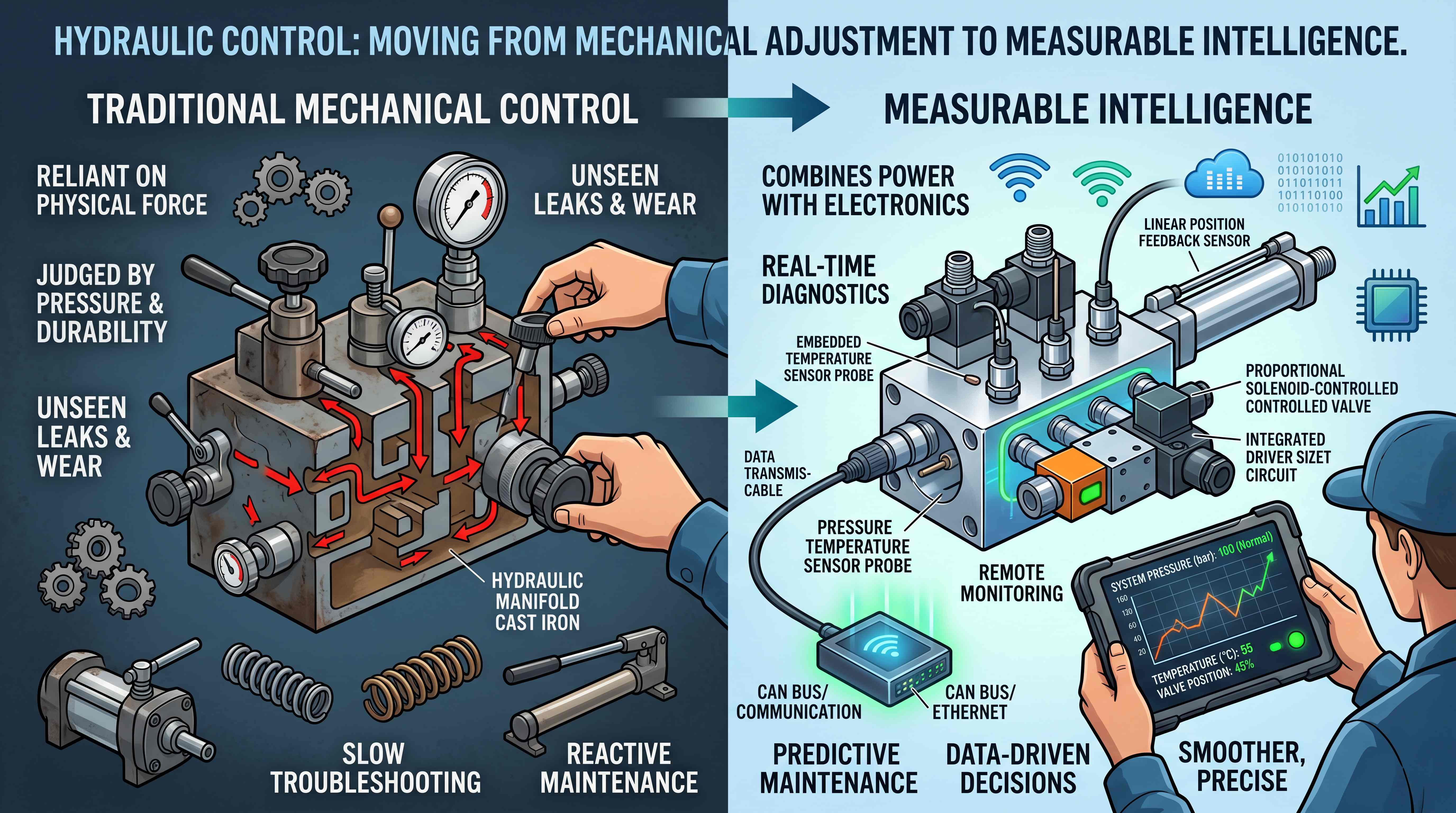
A hydraulic manifold may begin as a design drawing, but it becomes reliable only through manufacturing discipline. On paper, the circuit may look correct. The pressure line connects to the correct valve cavity. The tank return is properly routed. The actuator ports are labeled. Relief valves, check valves, flow controls and cartridge valves all have logical positions. But if the physical manifold is poorly machined, poorly cleaned or poorly tested, the hydraulic system can still fail.
This is why hydraulic manifold manufacturing should never be treated as ordinary metal processing.
A manifold block is not just a metal part with holes. It is a pressure-bearing hydraulic circuit. It contains internal passages that may carry high-pressure oil, low-pressure return flow, pilot signals and actuator flow. It may include cartridge valve cavities, threaded ports, sealing surfaces, cross-drilled passages, plugs, sensor ports and gauge ports. Any machining error, burr, contamination, seal damage or wrong material choice can affect the entire machine.
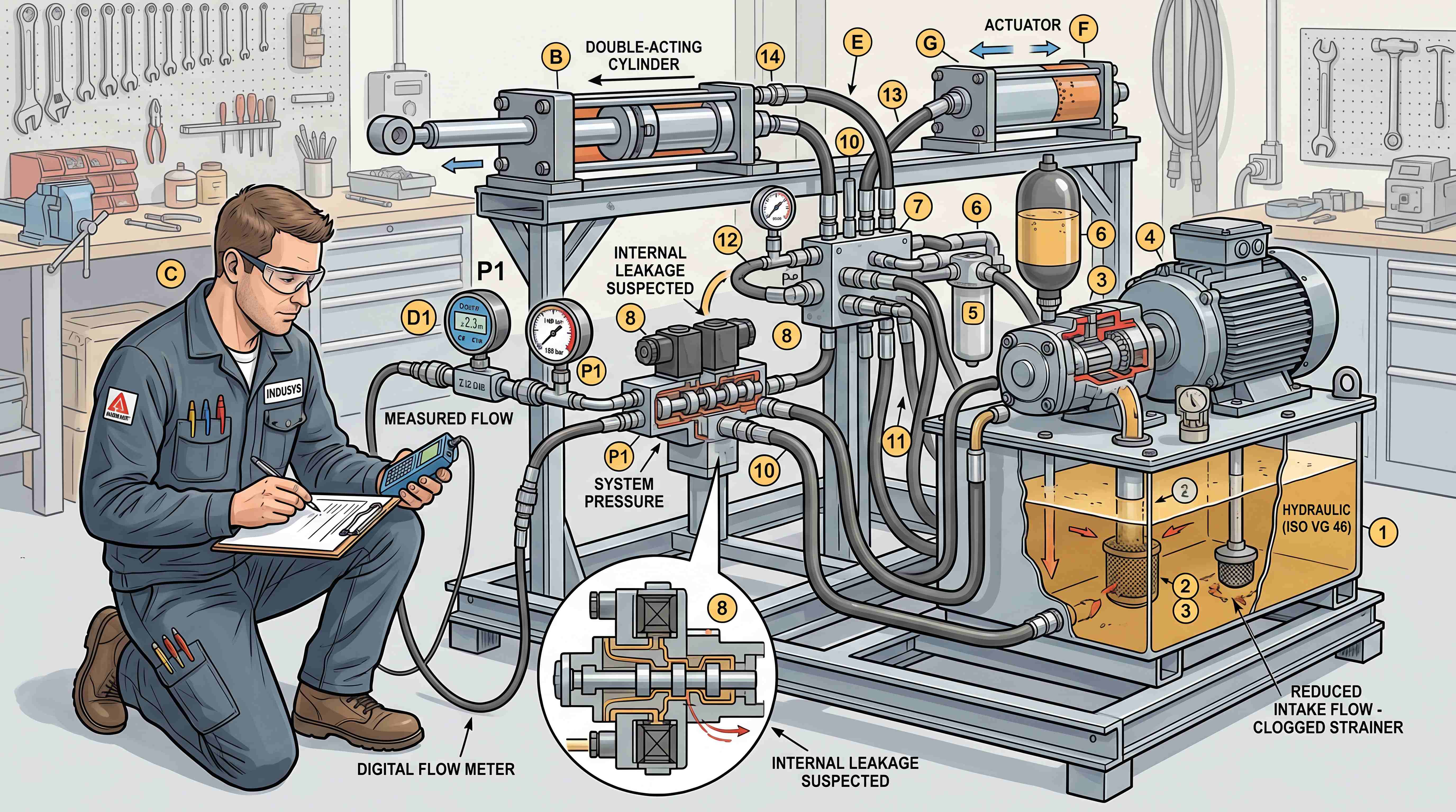
In many hydraulic failures, the visible symptom appears somewhere else. A cylinder moves slowly. A solenoid valve sticks. A relief valve fails to seal. A pump becomes noisy. Oil temperature rises. A cartridge valve leaks internally. A hose fitting leaks repeatedly. The first suspect may be the valve, the pump or the actuator, but the root cause may be inside the manifold block.
For example, a small metal chip left inside an internal passage can damage a valve seat. A burr near a cartridge cavity can cut an O-ring. An undersized passage can create pressure drop and heat. A wrong cavity depth can prevent a cartridge valve from sealing. A rough sealing surface can create external leakage. A weak material choice can fail under pressure spikes. A manifold that was never pressure tested may leave the factory with hidden defects.
This is why hydraulic manifold quality control is not a final inspection step only. It must run through the entire process: material selection, design review, CNC machining, deburring, cleaning, assembly, testing, marking and documentation.
A hydraulic system depends on control. The manifold is the physical architecture of that control. Manufacturing quality decides whether that architecture is trustworthy.
Manufacturing Quality Starts With Hydraulic Manifold Material

The first manufacturing decision is hydraulic manifold material. The material affects pressure capability, weight, machining performance, corrosion resistance, thread strength, sealing behavior, cost and application suitability.
An aluminum hydraulic manifold is widely used in many moderate-pressure applications. Aluminum is lightweight, easy to machine and suitable for compact hydraulic power units, mobile auxiliary circuits, laboratory systems and equipment where weight reduction matters. It is also attractive for custom manifolds because machining time can be shorter compared with steel.
However, aluminum is not suitable for every application. Its strength is lower than many steels. Thread strength, pressure spikes, shock loads and fatigue must be considered carefully. If the system operates at high pressure or experiences frequent shock loading, aluminum may not provide enough margin unless the design is specifically engineered for those conditions.
A steel hydraulic manifold is commonly used when pressure, durability and thread strength are more demanding. Steel blocks are heavier and generally harder to machine, but they offer higher strength and better resistance to severe hydraulic loads. Steel is often used in construction equipment, presses, heavy industrial systems, mobile machinery and applications where pressure spikes are expected.
Ductile iron may also be used for certain hydraulic manifold applications. It provides strength and durability and can be suitable for high-pressure valve bodies or manifold structures. Stainless steel is used when corrosion resistance is critical, such as marine, offshore, chemical or washdown environments.
Material choice should not be made only by comparing price. A cheaper material may increase risk if the application involves high pressure, vibration, heavy loads or harsh environments. A stronger material may be unnecessary if the system is moderate pressure and weight-sensitive.
Good material selection asks several questions.
What is the normal working pressure?
What is the maximum pressure?
Are there pressure spikes?
Is the manifold used indoors or outdoors?
Does weight matter?
What hydraulic fluid is used?
What seal materials are required?
Will the manifold be exposed to corrosion?
How often will fittings be removed and reinstalled?
Does the application involve safety-related load holding?
The right material supports the circuit, the machine and the lifecycle. The wrong material can turn a good manifold design into a reliability problem.
CNC Hydraulic Manifold Production Requires More Than Drilling Holes

A CNC hydraulic manifold is usually produced through milling, drilling, tapping, boring, reaming, cavity machining and surface finishing. Modern CNC equipment allows complex internal passages and precise valve cavities to be machined with repeatability. But CNC accuracy does not automatically guarantee hydraulic reliability. The process must be controlled around hydraulic function.
The most obvious machining requirement is dimensional accuracy. Threaded ports must match the specified standard. Valve cavities must meet the cartridge valve manufacturer’s geometry. Mounting surfaces must align with valves, subplates or machine frames. Plug holes must seal properly. Sensor and gauge ports must be positioned correctly.
Cartridge valve cavities are especially sensitive. A screw-in cartridge valve depends on correct cavity depth, diameter, sealing steps, port locations and surface finish. If any dimension is wrong, the valve may leak, fail to shift, experience excessive pressure drop or damage seals during installation. A cartridge may appear to fit physically but still fail hydraulically if the cavity is not correct.
Internal drilled passages also require careful planning. In many manifolds, passages intersect inside the block. These intersections must be placed accurately so oil flows through the intended path. If a drilled hole is too deep, too shallow or misaligned, it may connect to the wrong passage or fail to connect at all. A small error can change the circuit behavior completely.
Surface finish matters as well. Sealing surfaces must be smooth enough to prevent leakage. Valve mounting faces must be flat. O-ring grooves must be clean and correctly shaped. Sharp edges near seals can cut O-rings. Rough cavity surfaces can increase wear or prevent proper sealing.
Another manufacturing challenge is access. Some internal passages are created by cross-drilling and then closing unused openings with plugs. These plugs must be designed and installed correctly. A leaking cross-drill plug can cause external leakage or internal bypass.
Good hydraulic manifold machining is not only about making a part that matches a drawing. It is about preserving hydraulic logic in metal. Every hole has a function. Every cavity has a control purpose. Every seal land separates pressure zones. Every plug closes part of the manufacturing path.
A manifold is a machined hydraulic circuit, and machining must respect that reality.
Internal Passages Decide Pressure Drop, Heat and Response

Inside a hydraulic manifold, oil does not move through abstract lines on a schematic. It moves through physical passages with real diameter, length, bends, intersections and restrictions. These internal passages affect pressure drop, heat generation, response time and actuator behavior.
If a passage is too small for the required flow, oil must pass through a restriction. This creates pressure drop. Pressure drop means energy loss. Energy loss becomes heat. A machine may then run hotter, move slower or require more power from the pump.
This is why manifold passage sizing must be matched to flow rate. A compact manifold is not always a good manifold. A small block may look efficient, but if the internal flow paths are too restrictive, the system may suffer from poor performance.
Passage geometry also matters. Sharp intersections, unnecessary turns and long flow paths can increase pressure loss. In some circuits, a small pilot passage may be intentional. In other circuits, it may create delayed response or unstable valve operation. The designer and manufacturer must understand which passages are main flow paths and which are control signal paths.
Return passages are often underestimated. A return line may be low pressure, but it still needs enough capacity. Excessive return back pressure can affect actuator speed, valve shifting, counterbalance valve behavior and heat. In manifolds with multiple actuator returns, tank passages must be designed carefully.
Pilot passages are another critical detail. A pilot-operated valve depends on reliable pilot pressure. If a pilot passage is blocked, undersized, contaminated or leaking, the valve may not open or close properly. In load-sensing or pressure-compensated systems, signal passages are even more important.
Pressure spikes must also be considered. A passage that is adequate for steady flow may still experience severe shock loads if the actuator stops suddenly or a load changes quickly. The manifold material, wall thickness and passage spacing must support these conditions.
Manufacturing cannot fix a poor passage concept, but poor machining can ruin a good one. Accurate drilling, clean intersections and correct plugs are essential.
A hydraulic manifold should not only be compact. It should allow oil to move through the circuit with the right pressure, flow and control behavior.
Burrs Are Small Defects With Big Hydraulic Consequences
One of the most dangerous manufacturing problems in hydraulic manifolds is burr formation. Burrs are small pieces of metal left after drilling, milling, tapping or intersecting holes. They may appear minor, but in hydraulic systems they can cause serious failures.
A burr at a port edge can damage an O-ring during assembly. A burr inside a passage can break loose and travel through the system. A burr near a cartridge valve cavity can prevent sealing or interfere with valve movement. A burr in a pilot passage can restrict flow. A burr left at a drilled intersection can create turbulence, contamination or blockage.
In a hydraulic valve or manifold, even small particles matter. Many valves have tight clearances. Cartridge valves, proportional valves, check valves and relief valves can be sensitive to debris. If a burr breaks free and reaches a valve seat, the valve may leak. If it enters a spool clearance, the valve may stick. If it blocks an orifice, the system may lose control.
This is why deburring is a major part of hydraulic manifold quality control.
External deburring is relatively easy to see. Internal deburring is much harder. Cross-drilled passages may intersect deep inside the block where tools and eyes cannot easily reach. A manifold may look perfect from the outside while still containing sharp internal edges.
Manufacturers use different deburring methods depending on complexity, including manual deburring, brushing, abrasive flow processes, specialized tools, thermal deburring or controlled cleaning procedures. The correct method depends on material, geometry, tolerance and cleanliness requirements.
Deburring must be controlled carefully. Removing too little leaves risk. Removing too much may damage sealing edges or change dimensions. The goal is not simply to make the part look clean. The goal is to remove dangerous edges and loose material without harming functional surfaces.
For buyers evaluating a hydraulic manifold supplier, deburring capability is important. A supplier that treats manifolds as simple machined blocks may not control internal burrs properly. A supplier that understands hydraulics will know that burrs are not cosmetic defects. They are potential system failures.
Hydraulic Manifold Cleaning Is a Reliability Process
After machining and deburring, the manifold must be cleaned thoroughly. Hydraulic manifold cleaning is one of the most important steps in manufacturing because internal contamination can damage the entire hydraulic system.
Machining creates chips, particles, cutting fluid residue, abrasive dust and small debris. Tapping and drilling may leave particles inside passages. Deburring may create additional loose material. If these contaminants remain inside the manifold, they can enter valves, pumps, cylinders and hoses after installation.
A new manifold that is not clean can cause failure before the machine has done any real work.
Cleaning must reach internal passages, not only external surfaces. A manifold may be washed on the outside and still contain chips inside cross-drilled holes. Proper cleaning may include flushing, high-pressure washing, ultrasonic cleaning, solvent cleaning, air blowing, particle inspection and protective packaging.
The cleaning process should match the required cleanliness level of the system. A simple low-pressure circuit may not require the same cleanliness as a proportional valve manifold or servo-controlled system. However, all hydraulic manifolds require disciplined cleaning because oil contamination is a leading cause of hydraulic valve failure.
Drying and protection are also important. After cleaning, moisture must be removed to prevent corrosion and fluid contamination. Ports may need protective plugs. Open cavities should be protected from dust. Clean manifolds should not be placed on dirty benches or handled carelessly before assembly.
Cleaning is not complete if the part becomes contaminated again during storage, transport or assembly. A clean manufacturing process requires clean handling.
For OEM applications, cleanliness should be defined in the quality requirements. The buyer and supplier should agree on acceptable particle levels, cleaning method, packaging and inspection approach when the application is sensitive.
Hydraulic reliability often depends on invisible cleanliness. A manifold can look bright and well-machined while still being unsafe for the hydraulic circuit if internal passages are dirty.
Pressure Testing Confirms More Than Strength
Hydraulic manifold pressure testing is not only about proving that the block does not burst. It verifies sealing, passage integrity, plug performance, valve cavity function and circuit correctness.
A manifold may be pressure tested in different ways depending on application. A proof test may apply pressure above normal working pressure to confirm structural integrity. A leakage test may check whether oil escapes externally. A circuit test may confirm that oil flows through the intended internal passages. An assembled manifold test may verify valve functions, relief settings, solenoid operation, check valve sealing or flow control behavior.
Pressure testing is especially important for high-pressure systems, safety-related systems and custom manifolds. When a manifold is unique to a machine, testing helps confirm that the design and machining match the circuit.
External leakage testing can reveal problems around plugs, threaded ports, O-ring seals, gauge ports, sensor ports and valve mounting surfaces. Internal leakage testing may require more specialized methods. The goal is to confirm that pressure zones remain separated and that the manifold does not create unintended bypass paths.
Testing also helps detect machining errors. If a passage is missing, blocked or incorrectly connected, pressure behavior may reveal the problem. A manifold that passes visual inspection may still fail hydraulic testing if an internal hole was drilled incorrectly.
For manifolds assembled with cartridge valves, testing can also verify that each valve is installed in the correct cavity. A relief valve should open at the proper setting. A check valve should block reverse flow. A solenoid cartridge should shift when energized. A flow control valve should regulate flow as expected.
Testing should be documented. Pressure levels, test duration, leakage criteria, fluid used and test results should be recorded when the application requires traceability. This documentation is especially valuable for OEMs and critical equipment.
A manifold that is not tested may still work, but testing reduces uncertainty. In hydraulic systems, uncertainty often becomes downtime.
Quality Control Must Cover Design, Machining and Assembly
Hydraulic manifold quality control should not be limited to a final visual check. A good quality system covers the entire manufacturing chain.
Design review is the first control point. The hydraulic schematic should be checked against the manifold drawing. Port labels, valve functions, pressure paths, tank paths, actuator ports, pilot passages and plug locations should be verified before machining begins.
Material inspection is the second control point. The material grade, heat treatment condition and supplier certification may need to be confirmed depending on application. Material defects can create machining problems or pressure risk.
Machining inspection is the third control point. Critical dimensions should be measured. Valve cavities, threads, port depths, mounting surfaces, O-ring grooves and plug holes should be checked. Coordinate measuring machines, gauges, thread gauges and cavity tools may be used.
Deburring inspection is the fourth control point. Internal and external burrs should be controlled. This is difficult but essential. Some inspection may require borescopes, airflow checks or process validation.
Cleaning inspection is the fifth control point. The manifold should meet cleanliness requirements before assembly. If contamination-sensitive valves are used, cleanliness becomes even more important.
Assembly control is the sixth point. Cartridge valves, plugs, seals, sensors and fittings must be installed correctly. Torque values must be followed. Seal materials must match the hydraulic fluid. Coils must match voltage. Adjustments must match specifications.
Pressure testing and functional testing are final control points. They confirm that the manifold holds pressure and that the hydraulic logic works as intended.
Documentation is also part of quality. A manifold without correct labels, drawings or part numbers may create service problems even if it was manufactured correctly.
Quality control is not only about preventing defective parts from shipping. It is about ensuring that the manifold can perform as a reliable hydraulic control component throughout its service life.
Assembly Errors Can Ruin a Correctly Machined Manifold
Even if the manifold block is machined correctly, assembly errors can create failure. Many hydraulic manifold problems are caused not by the block itself but by wrong seals, wrong cartridge valves, wrong torque, wrong plug installation or poor cleanliness during assembly.
Cartridge valves are a common source of assembly risk. A manifold may contain several similar-looking cartridges. One may be a relief valve, another a check valve, another a flow control valve and another a solenoid valve. If they are installed in the wrong cavities, the circuit changes. The machine may lose pressure, fail to hold load, overheat or move unpredictably.
Seal installation also matters. O-rings and backup rings must be the correct size and material. If a seal is twisted, cut, pinched or placed in the wrong groove, it may leak externally or internally. Seal damage may not appear immediately. It may fail under pressure after installation.
Torque values are important. Under-tightening may allow leakage or loosening. Over-tightening may damage threads, distort valve bodies or crush seals. Cartridge valves and plugs should be installed according to specified torque, not by guesswork.
Clean assembly practices are essential. A technician can contaminate a clean manifold by placing cartridges on a dirty bench, using dirty tools, leaving ports open or applying excess thread sealant. Thread sealant must be used carefully because loose sealant can block small passages.
Electrical assembly matters for solenoid manifolds. Coil voltage, connector orientation, cable routing and protection from moisture or vibration should be checked. A hydraulic problem may begin as an electrical assembly mistake.
Good assembly control includes checklists, part verification, torque records, clean work areas and final inspection. For OEMs, this process should be repeatable, not dependent only on individual experience.
A correctly machined manifold can fail if assembled carelessly. Manufacturing quality continues until the manifold is fully built, tested and protected.
Marking, Labeling and Documentation Improve Long-Term Service
A hydraulic manifold is easier to manufacture than it is to troubleshoot without documentation. Marking and documentation are not small details. They are part of lifecycle reliability.
Port labels help technicians connect hoses correctly. Common markings include P for pressure, T for tank, A and B for actuator ports, LS for load sense, G for gauge, DR for drain and pilot labels where needed. Clear markings reduce installation errors.
Valve cavity labels help maintenance teams identify which cartridge performs which function. A service technician should not need to guess whether a cartridge is a relief valve, check valve, flow control valve or sequence valve. Labels or a cavity map can prevent wrong replacements.
Pressure settings should be documented. Relief valves, reducing valves, counterbalance valves and sequence valves may require specific settings. If these values are not recorded, field adjustment becomes risky.
Electrical information should also be recorded. Solenoid coil voltage, connector type and wiring information should be available. A wrong-voltage coil can fail quickly.
A good manifold documentation package may include hydraulic schematic, manifold drawing, bill of materials, cavity map, port map, torque values, seal kit information, pressure settings, test report and replacement part list.
For a hydraulic manifold supplier, documentation quality reflects professionalism. A supplier that provides only a machined block leaves the buyer with future service risk. A supplier that provides clear documentation supports the entire machine lifecycle.
Documentation also helps SEO and B2B marketing because it proves engineering seriousness. In industrial buying, trust often comes from details. Buyers want to know that the supplier can support repeatability, quality control and after-sales service, not only produce metal parts.
A manifold should be understandable years after it is installed. Good marking and documentation make that possible.
How to Evaluate a Hydraulic Manifold Supplier
Choosing a hydraulic manifold supplier is not only about asking for a quotation. A low price does not guarantee correct engineering, clean machining or reliable pressure performance. Buyers should evaluate capability across several dimensions.
The first dimension is engineering understanding. Does the supplier understand hydraulic circuits, valve functions, cartridge cavities, pressure drop, load control and service requirements? Or do they only machine according to a drawing without hydraulic knowledge?
The second dimension is material control. Can the supplier provide suitable aluminum, steel, ductile iron or stainless steel options? Can they explain why one material fits the application better than another?
The third dimension is machining capability. Do they have CNC equipment suitable for manifold blocks? Can they machine accurate cartridge valve cavities, deep passages, threaded ports and sealing surfaces?
The fourth dimension is deburring and cleaning. How do they remove internal burrs? How do they clean drilled passages? How do they prevent contamination after cleaning?
The fifth dimension is testing. Can they perform pressure testing, leakage testing and functional testing when required? Can they provide test reports?
The sixth dimension is assembly support. Can they assemble cartridge valves, plugs, coils, sensors and fittings? Do they follow torque and cleanliness procedures?
The seventh dimension is documentation. Can they provide drawings, port labels, valve maps, part lists and settings?
The eighth dimension is repeatability. For OEMs, can the supplier produce the same manifold consistently across batches?
The ninth dimension is communication. Can they review the application, ask technical questions and identify risks before production?
The final dimension is service support. If a problem occurs, can they help analyze it, or do they only sell replacement parts?
A good hydraulic manifold supplier should be a manufacturing partner, not just a machine shop.
Common Manufacturing Mistakes That Cause Hydraulic Problems
Several manufacturing mistakes appear repeatedly in hydraulic manifold production.
One mistake is selecting material only by cost. An aluminum manifold may be economical, but not suitable for severe shock pressure. A steel manifold may be strong, but unnecessary for a lightweight moderate-pressure system.
Another mistake is ignoring internal passage sizing. If passages are too small, the system may suffer pressure drop and heat.
A third mistake is inaccurate cartridge cavity machining. If the cavity does not match the valve specification, sealing and function may fail.
A fourth mistake is poor internal deburring. Burrs can break loose and damage valves.
A fifth mistake is weak cleaning. Chips and particles left inside the manifold can cause immediate contamination problems.
A sixth mistake is poor plug installation. Cross-drill plugs must seal reliably under pressure.
A seventh mistake is using wrong seals or damaged O-rings during assembly. This can cause internal or external leakage.
An eighth mistake is not pressure testing custom manifolds. Hidden machining errors may remain undiscovered until the machine fails.
A ninth mistake is failing to label ports and valve cavities. Service errors become more likely.
A tenth mistake is producing a manifold without understanding the hydraulic circuit. A block can be machined correctly according to a flawed concept and still fail in application.
Avoiding these mistakes requires treating manifold manufacturing as hydraulic engineering, not just metal cutting.
Manufacturing Quality Affects the Total Cost of the Hydraulic System
A high-quality manifold may cost more than a basic machined block, but poor manufacturing can cost much more over time.
A leaking manifold can cause downtime, oil loss, cleanup cost and safety risk. A contaminated manifold can damage valves, pumps and cylinders. A wrongly machined cavity can require rework or replacement. A block without documentation can make troubleshooting slow. A manifold that creates pressure drop can waste energy and generate heat. A poorly tested manifold can fail after installation, when repair cost is much higher.
The real cost of a manifold includes more than its purchase price. It includes installation time, leak risk, machine downtime, warranty claims, maintenance labor, oil cleanliness, troubleshooting time and customer confidence.
For OEM manufacturers, manifold quality affects production consistency. If each batch of manifolds varies, machine performance varies. If ports are not labeled consistently, assembly errors increase. If internal cleanliness is poor, early-life failures may occur.
For end users, manifold quality affects reliability. A machine may operate in a harsh environment for years. The manifold must hold pressure, protect valves and support maintenance.
For suppliers, quality affects reputation. Industrial buyers remember whether components caused downtime. A manifold is often hidden inside a machine, but when it fails, the consequences are highly visible.
Quality is not an extra feature. It is part of the hydraulic system’s total value.
Conclusion: A Hydraulic Manifold Is a Precision Control Component
A hydraulic manifold may look like a machined metal block, but its role is much more important. It is a pressure-bearing, flow-directing, valve-integrating control component. Its manufacturing quality directly affects leakage, contamination, pressure stability, valve performance, heat generation and long-term machine reliability.
Good hydraulic manifold manufacturing starts with the right hydraulic manifold material. An aluminum hydraulic manifold may be ideal for lightweight moderate-pressure systems, while a steel hydraulic manifold may be better for high pressure, shock loads and heavy-duty applications.
A reliable CNC hydraulic manifold requires accurate hydraulic manifold machining, correct valve cavities, clean internal passages, proper sealing surfaces and controlled plug locations. But machining is only one part of the story. Deburring, hydraulic manifold cleaning, assembly discipline, labeling and hydraulic manifold pressure testing are equally important.
Strong hydraulic manifold quality control connects every step from design review to final testing. It prevents hidden defects, protects hydraulic valves and supports predictable machine performance.
For buyers, choosing the right hydraulic manifold supplier means looking beyond price. The supplier should understand hydraulic circuits, material selection, machining accuracy, internal cleanliness, pressure testing and documentation.
In hydraulic systems, reliability is built before the machine runs. It is built into the material, the cavity, the passage, the seal, the cleaning process and the test report. That is why hydraulic manifold manufacturing is not just production work. It is the foundation of controlled hydraulic motion.
#HydraulicManifoldMaterial
#CNCHydraulicManifold
#HydraulicManifoldMachining
#HydraulicManifoldCleaning
#HydraulicManifoldPressureTesting
#HydraulicManifoldQualityControl
#AluminumHydraulicManifold
#SteelHydraulicManifold
#HydraulicManifoldSupplier
#HydraulicValves
#HydraulicManifolds
#IndustrialHydraulics
#MobileHydraulics
#FluidPower