What Are Hydraulic Valves and Manifolds? A Practical Guide to Hydraulic Control Systems
What Hydraulic Valves and Manifolds Really Do in a Machine
In any hydraulic machine, power is not useful until it can be controlled. A hydraulic pump may generate flow, a motor may convert fluid power into rotation, and a cylinder may push or lift a heavy load. But without the right control components, the system would be difficult to start, stop, reverse, slow down, protect, or coordinate.
This is where hydraulic valves and manifolds become essential.
A hydraulic valve controls how hydraulic oil moves through a circuit. It can direct oil to one side of a cylinder, limit maximum pressure, regulate flow speed, prevent reverse flow, or hold a load in position. A hydraulic manifold, often called a hydraulic manifold block, brings multiple valves and flow paths together inside one compact block. Instead of connecting every valve with external hoses, tubes and fittings, the manifold integrates part of the circuit into a machined body with internal passages.
In simple terms, hydraulic valves decide what the fluid should do. Hydraulic manifolds help organize where the fluid should go.
Together, they form the control center of a hydraulic control system. They influence machine safety, movement accuracy, energy efficiency, serviceability, installation complexity and long-term reliability. In mobile equipment, industrial presses, agricultural machinery, lifting platforms, forklifts, marine systems and manufacturing equipment, the quality of valve and manifold design often determines whether the machine feels stable, responsive and dependable.
Many people first understand hydraulic systems by looking at visible parts: pumps, cylinders, hoses and oil tanks. But experienced engineers and maintenance teams know that the real behavior of the machine is usually hidden inside the valve group. If a cylinder moves too fast, a load drifts down, a hydraulic motor stops unexpectedly, or a machine overheats under load, the root cause is often connected to valve function, manifold layout, circuit design or oil contamination.
That is why understanding hydraulic valves and manifolds is not only useful for engineers. It is also important for equipment buyers, maintenance teams, OEM designers, parts suppliers and anyone who needs to evaluate hydraulic system performance.

Hydraulic Power Needs Control, Not Just Pressure
Hydraulic systems are valued because they can transmit large amounts of power through pressurized fluid. Compared with purely mechanical systems, hydraulics can deliver high force in compact spaces. Compared with many electric-only solutions, hydraulics are still widely used where heavy loads, shock resistance, rugged operation and high force density are required.
However, pressure alone does not make a machine work correctly.
A hydraulic pump creates flow. Resistance to that flow creates pressure. But a machine needs more than pressure. It needs controlled motion. A loader arm must lift smoothly. A press must apply force at the right time. A steering system must respond predictably. A clamp must hold position without slipping. A lift platform must not drop suddenly when the pump stops.
These actions depend on the control logic inside the hydraulic circuit.
A directional control valve may send oil to extend or retract a cylinder. A pressure relief valve may protect the system from excessive pressure. A flow control valve may regulate actuator speed. A check valve may stop reverse flow. A counterbalance valve may prevent a load from falling out of control. A hydraulic cartridge valve may perform one of these functions inside a compact manifold cavity.
The relationship between pressure, flow and direction is central to hydraulic system design. Pressure relates to force. Flow relates to speed. Direction relates to movement path. Valves manage these three factors, while manifolds arrange them into a practical and maintainable system.
If a system is designed only to “produce pressure,” it may still perform poorly. It may generate heat, waste energy, suffer from pressure spikes, leak at multiple connections, or create jerky movements. A better hydraulic system is not simply stronger; it is better controlled.
What Is a Hydraulic Valve?
A hydraulic valve is a component that controls hydraulic oil within a circuit. Depending on its function, it may control direction, pressure, flow rate, sequence, load holding or safety protection. The valve may be manually operated, mechanically actuated, hydraulically piloted, electrically controlled or proportionally controlled.
In practical machine language, a hydraulic valve answers questions like:
Where should the oil go?
How much oil should pass through?
How much pressure is allowed?
Should the actuator move, stop, hold or return?
Should the system protect itself if pressure becomes too high?
Should a load remain locked when the pump is not running?
Because there are many control tasks, there are also many hydraulic valve types. A small agricultural machine, a compact loader, an industrial press and a marine lifting system may all use hydraulic valves, but the circuit logic and valve selection can be very different.
The most common misunderstanding is treating hydraulic valves as interchangeable hardware. In reality, a valve is part of a system. Its flow capacity, pressure rating, spool configuration, port pattern, actuation method, leakage characteristics, material, seal type and response behavior all affect the final machine.
A valve that looks suitable by size may be wrong for the circuit. A valve with the correct pressure rating may still cause excessive pressure drop. A solenoid valve may shift correctly in a clean test bench but fail in a contaminated field environment. A manual valve may be simple and reliable but unsuitable where electronic automation is required.
Therefore, valve selection should start from machine function, not from part appearance.
Main Hydraulic Valve Types and Their Roles
Although the first article in this category should not become a full valve catalog, it is important to understand the basic families of hydraulic valves. Each family solves a different control problem.
A directional control valve controls the path of hydraulic oil. It decides whether an actuator extends, retracts, rotates, stops or remains in neutral. Directional valves are common in cylinders, motors, lifting arms, steering systems and many mobile machines. Their spool configuration is especially important because the neutral position can change how oil returns to tank, holds pressure or blocks movement.
A pressure relief valve protects the system by limiting maximum pressure. When pressure rises beyond a set value, the valve opens to divert oil and prevent damage to pumps, hoses, seals, actuators or structural components. Relief valves are not just safety accessories; they are critical elements in pressure control and system protection.
A flow control valve regulates the rate of oil flow. Because actuator speed is directly related to flow, this valve can help control how fast a cylinder extends or how quickly a hydraulic motor turns. Flow control becomes especially important when smooth movement, repeatable speed or controlled descent is required.
Check valves allow oil to flow in one direction while blocking reverse flow. They are simple, but they are widely used in load holding, circuit isolation and return-line protection.
Counterbalance valves and load-holding valves are used where gravity or external force can drive the actuator. These valves are essential in lifting equipment, cranes, platforms and any application where uncontrolled movement could create safety risks.
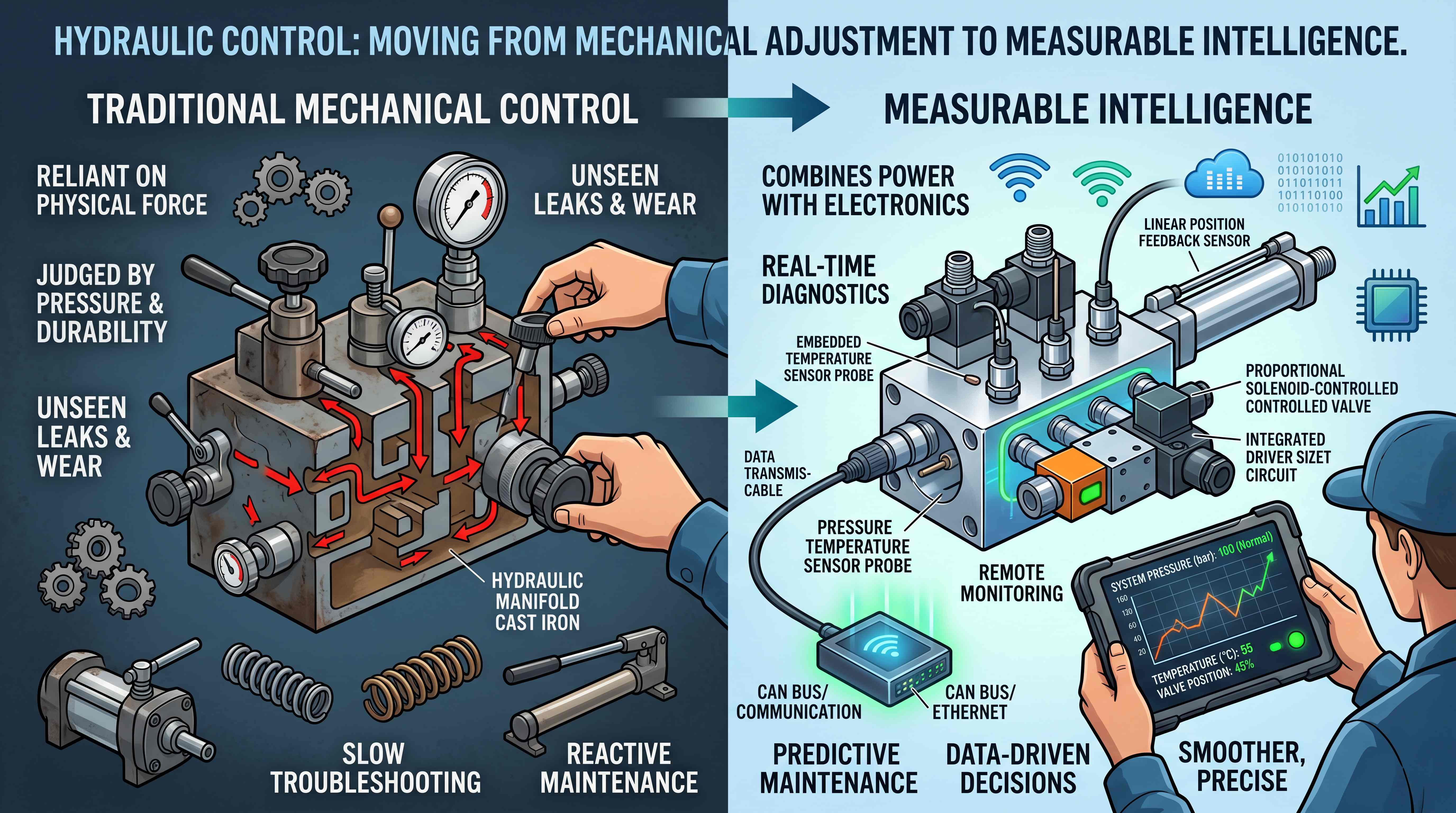
Proportional valves allow more precise control than simple on/off valves. They are commonly used when smooth acceleration, variable speed or electronic control is required. As machines become more automated, proportional and electrohydraulic control are becoming more important in advanced hydraulic systems.
A hydraulic cartridge valve is a compact valve element designed to fit into a cavity, often inside a manifold block. Cartridge valves are widely used because they support modular circuit design. They can provide pressure, flow, direction or check functions while keeping the system compact.
These categories show why the phrase “hydraulic valve” is broad. The right question is not simply “Which valve do I need?” The better question is: “What control function does the machine need, and how should that function be integrated into the system?”
What Is a Hydraulic Manifold Block?

A hydraulic manifold block is a machined block that contains internal passages for hydraulic oil. It connects multiple valves, ports and flow paths inside a single structure. Manifolds can be made from aluminum, steel, ductile iron or other suitable materials depending on pressure, environment, fluid compatibility and application requirements.
The manifold may include cavities for cartridge valves, mounting surfaces for directional valves, ports for hoses or tubes, test points, plugs, pressure sensors and auxiliary components. In a well-designed manifold, the internal oil paths replace part of the external plumbing that would otherwise require hoses, fittings and separate valve bodies.
This has several advantages.
First, the system becomes more compact. A machine with limited installation space can use a manifold to combine many control functions into a smaller footprint.
Second, the number of external leak points is reduced. Every hose connection and threaded fitting is a potential leakage point. By moving flow paths inside the block, a manifold can reduce the number of external connections.
Third, assembly becomes more repeatable. This is especially important for OEM production. A standard or custom hydraulic manifold allows the same circuit to be installed consistently across multiple machines.
Fourth, service and troubleshooting can become easier when the manifold is well documented. Technicians can identify valve cavities, test ports and circuit functions more efficiently than tracing a complex network of external hoses.
Fifth, manifolds support cleaner machine design. Instead of scattered valves mounted in different locations, the control logic can be centralized.
However, a manifold is not automatically better just because it is compact. Poor internal passage design can create pressure drop, heat generation, difficult maintenance access or confusing service procedures. This is why manifold design must be treated as part of the overall hydraulic system design, not just a machining task.
Why Valves and Manifolds Are Often Designed Together
Hydraulic valves and manifolds are closely connected because many modern hydraulic systems are no longer built from separate inline valves alone. Instead, engineers often integrate multiple valves into one manifold assembly.
This is especially common with cartridge valves. A hydraulic cartridge valve can be installed into a cavity within the manifold. Multiple cartridge valves can then work together as a complete circuit. For example, one manifold may include a relief valve, check valve, flow control valve, directional control function and pressure test point.
This integrated approach allows designers to build compact control systems for mobile and industrial machinery. It also allows machine builders to reduce hose routing, simplify installation and protect components inside a more organized layout.
But the key point is that a manifold is not just a metal block with holes. It is a physical representation of the hydraulic circuit. The internal drilling paths, cavity locations, port sizes, valve positions and mounting surfaces all reflect the intended control logic.
When valves and manifolds are designed together, the system can be optimized for pressure drop, service access, actuator response, safety function and manufacturability. When they are treated separately, problems can appear later in the machine lifecycle. The system may technically work, but it may be hard to assemble, hard to diagnose, prone to leaks, or difficult to modify.
This is why experienced hydraulic designers often begin with the circuit, then choose valves, then design the manifold. The order matters. If the manifold is designed before the circuit is fully understood, the final system may require compromises that affect reliability or performance.
Separate Valves vs Integrated Manifold Systems
Traditional hydraulic systems often use separate valves connected by hoses and fittings. This method can still be practical in many situations, especially for simple machines, prototypes, repairs or low-volume equipment. Separate valves are easy to identify and replace. They can also be flexible when the circuit is frequently modified.
However, as machines become more compact and functions become more complex, separate valve arrangements can create problems. External hoses take space. Fittings increase leak risk. Assembly takes time. Troubleshooting can become difficult when hoses overlap or when the circuit is not clearly labeled. Repeated production can also become inconsistent if technicians route lines differently.
Integrated manifold systems solve many of these issues by bringing multiple control functions into one block.
For OEM equipment, a manifold can improve consistency. Every machine can receive the same valve layout, port orientation and circuit arrangement. For mobile machinery, the compact structure can fit into tight chassis areas. For industrial systems, manifolds can reduce installation time and improve the cleanliness of the hydraulic power unit.
That said, integration must be planned carefully. A manifold assembly may be less flexible if the circuit changes later. It also requires accurate drawings, proper machining, correct cavity standards and careful valve compatibility checks. If a valve is installed in the wrong cavity or a plug is misplaced, troubleshooting can become difficult.
The best choice depends on application stage and system complexity. A prototype may benefit from separate valves. A mature OEM product may benefit from a custom manifold. A maintenance replacement may require matching an existing valve block. A high-volume machine may justify more advanced manifold optimization.
How Hydraulic Valves and Manifolds Affect Machine Performance
Hydraulic valves and manifolds influence machine performance in ways that are not always obvious from a parts list.
Movement smoothness is one example. If flow is not controlled properly, a cylinder may jerk, surge or move unevenly. If a directional valve shifts too abruptly, the actuator may experience shock. If a proportional control strategy is used correctly, the same machine may move more smoothly and predictably.
Load holding is another example. If the circuit lacks proper check or counterbalance control, a lifted load may drift or drop. This can create safety risks and damage equipment. A well-designed manifold may integrate load-holding functions close to the actuator circuit.
System heat is also affected by valve and manifold choices. Excessive pressure drop across undersized valves, sharp internal passages or unnecessary throttling can convert useful hydraulic energy into heat. Overheating reduces oil life, damages seals and lowers system efficiency.
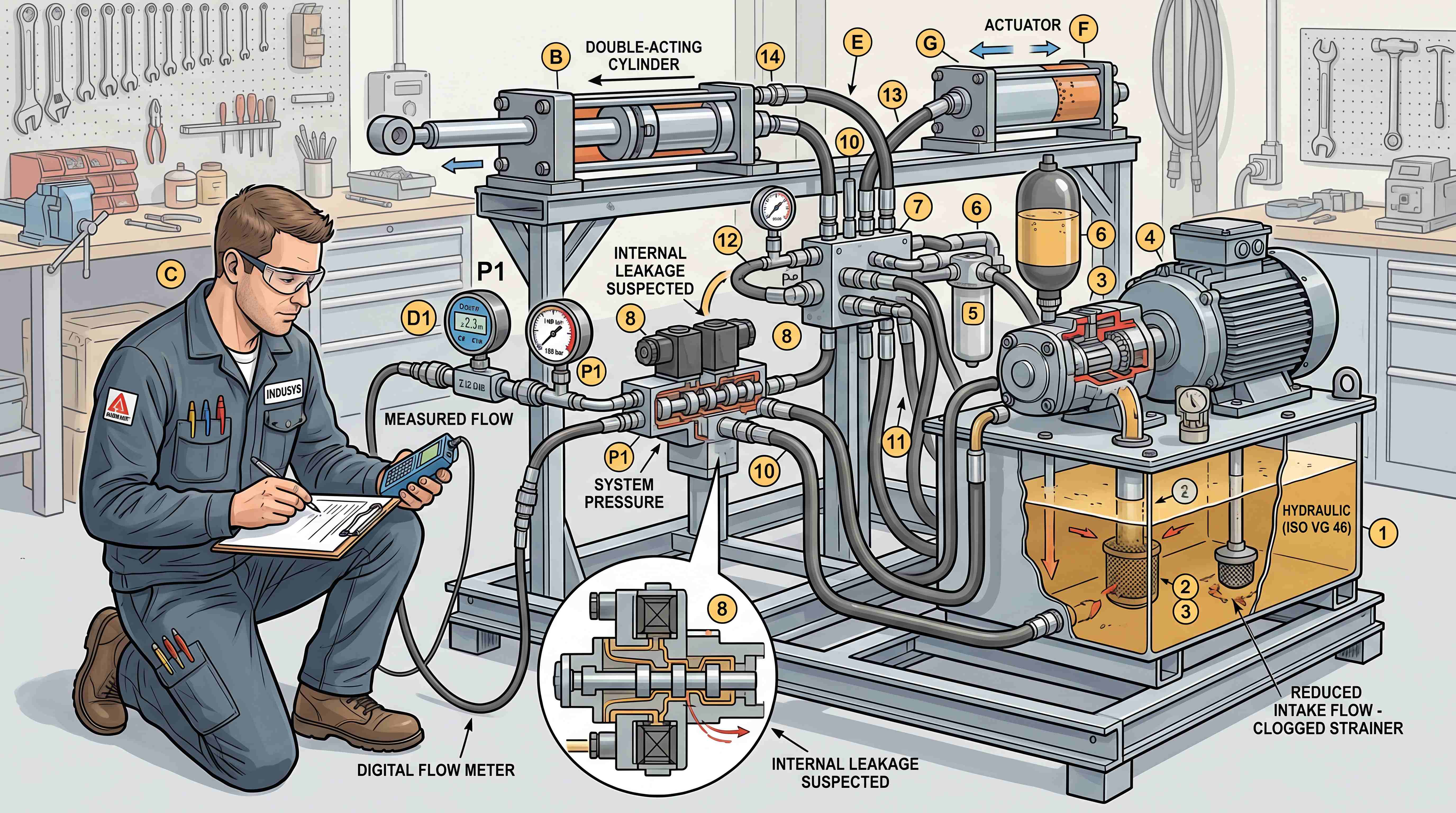
Serviceability is another performance factor. A machine that is easy to diagnose spends less time out of service. Clear manifold labeling, accessible test ports and logical valve arrangement help technicians identify pressure, flow and control issues faster.
Leakage control is also important. External leakage creates mess, environmental concerns, safety hazards and maintenance cost. Internal leakage can reduce holding ability, speed consistency and system efficiency. Proper valve selection, machining quality, sealing design and contamination control all influence leakage behavior.
Finally, equipment reliability depends on how well the control components match real working conditions. A valve that performs well in a clean indoor environment may not last in a dusty mobile machine if contamination protection is poor. A manifold designed for moderate pressure may not be suitable for shock-loaded equipment. A circuit designed without enough attention to pressure spikes may damage components over time.
In short, hydraulic valves and manifolds shape the real behavior of the machine. They are not just accessories in the hydraulic system. They are part of the machine’s operating personality.
Common Applications of Hydraulic Valves and Manifolds
Hydraulic valves and manifolds are used across a wide range of industries because fluid power remains important wherever heavy force, rugged operation or compact actuation is required.
In construction machinery, valves and manifolds control boom movement, bucket tilt, steering, braking, attachments and auxiliary circuits. These machines often face shock loads, vibration, contamination and outdoor conditions. Valve reliability and load control are critical.
In agricultural equipment, hydraulic systems control implements, steering, lifting arms, seeders, sprayers and harvesting functions. These applications often require simple operation, durable components and easy field maintenance. A hydraulic manifold block may help reduce hose complexity on compact equipment.
In forklifts and material handling machines, hydraulic valves control lifting, tilting, side shifting and steering functions. Smooth control is important because unstable movement can affect load safety. Pressure control and load-holding functions are especially relevant.
In industrial presses, hydraulic systems must generate controlled force. Valves and manifolds manage pressure build-up, holding, decompression, return movement and safety functions. In these applications, repeatability and pressure stability matter.
In lifting platforms and access equipment, valve design directly affects safety. Counterbalance, check and emergency lowering functions may be integrated into manifold systems. The circuit must prevent uncontrolled descent and support predictable operation.
In marine, mining and heavy industrial systems, valves and manifolds must withstand harsh environments. Material selection, corrosion resistance, sealing reliability and service access become more important.
These applications show why the same keywords can represent very different engineering requirements. A flow control valve for a small agricultural attachment is not the same design challenge as a flow control function inside a high-pressure industrial press. A custom hydraulic manifold for a compact loader is different from a manifold for a factory hydraulic power unit.
The application defines the priorities.
What Buyers Should Know Before Choosing Hydraulic Valves and Manifolds
For buyers and equipment teams, choosing hydraulic valves and manifolds should not start with price alone. Price matters, but the wrong control component can create much higher costs through downtime, leakage, poor movement, safety risk or redesign.
Before choosing a valve or manifold, several questions should be answered.
What pressure range will the system operate in?
What flow rate is required for each actuator?
What type of actuator is being controlled?
Is the circuit open center, closed center or load sensing?
Does the system need manual, electric, pilot or proportional control?
Is load holding required?
Will the machine operate outdoors, in high dust, in cold weather or under vibration?
Is the design for repair, prototype or repeat production?
Does the equipment need a standard manifold or a custom hydraulic manifold?
How will technicians test pressure and diagnose faults later?
These questions are practical because they connect product selection to real machine behavior. A valve may meet the catalog pressure rating but still be wrong if the spool configuration does not match the pump circuit. A manifold may appear compact but create maintenance problems if test points are inaccessible. A cartridge solution may be efficient but only if the cavity standard, flow rating and circuit logic are correct.
For OEM buyers, documentation is also important. Drawings, hydraulic schematics, cavity information, port labeling, torque requirements, seal kits and replacement part data all affect long-term service. A hydraulic component is not fully useful if technicians cannot understand or maintain it.
For replacement buyers, matching the old part is not always enough. Sometimes the old system failed because the original valve was contaminated, undersized, overheated or misapplied. In these cases, a better understanding of the circuit may be needed before replacement.
Why Hydraulic System Design Is More Than Component Selection

A strong hydraulic system is not created by selecting high-quality components one by one. It is created by making those components work together.
This is where hydraulic system design becomes important. The pump, valves, manifold, actuators, reservoir, filters, hoses, sensors and control logic must support the same performance goal. If one part is mismatched, the whole system may suffer.
For example, a high-quality directional valve cannot solve poor filtration. A well-machined manifold cannot compensate for an incorrect relief setting. A flow control valve cannot deliver stable speed if pump flow varies too much under load. A compact valve block may reduce leakage points, but if the internal passages are too restrictive, the system may generate heat.
Good hydraulic design balances several factors at the same time: pressure capacity, flow demand, response time, heat generation, energy efficiency, contamination control, serviceability, safety and cost.
This is also why hydraulic valves and manifolds should be considered early in machine development. If they are treated as final accessories after the frame, power unit and actuator layout are already fixed, the designer may have limited room to create an efficient circuit. Early planning allows better port orientation, shorter hose routing, cleaner installation and easier service access.
For machinery manufacturers, this can affect production efficiency. A well-planned manifold assembly can reduce assembly steps, lower fitting count and make quality control more repeatable. For maintenance teams, it can reduce downtime. For end users, it can improve machine reliability and operating confidence.
A Practical Way to Understand the Whole System
For readers who are new to this topic, the easiest way to understand hydraulic valves and manifolds is to imagine a machine movement.
A cylinder needs to lift a load. The pump sends oil into the system. A directional valve decides whether oil goes to the cap end or rod end of the cylinder. A pressure relief valve protects the circuit if the load is too heavy. A flow control valve may slow the lifting or lowering speed. A check or counterbalance valve may keep the load from dropping when the control is released. A manifold block may contain several of these functions in one compact assembly.
This simple movement requires multiple control decisions. The machine must move, stop, hold, protect itself and respond predictably. That is why hydraulic control is not just about supplying oil. It is about managing energy safely and intelligently.
When the circuit is simple, separate components may be enough. When the machine becomes more compact, more automated, more safety-sensitive or more production-oriented, integrated valve and manifold design becomes more valuable.
This is the core reason why hydraulic valves and manifolds are still essential in modern machinery. Even as electronic controls become more advanced, fluid power still needs physical pathways, pressure control and reliable valve functions. Electronics can send commands, but valves and manifolds still execute much of the hydraulic logic.
Conclusion: Valves and Manifolds Are the Control Logic of Hydraulic Machines
Hydraulic pumps create flow. Actuators create motion. But hydraulic valves and manifolds decide how that motion happens.
A valve controls direction, pressure, flow, load holding or safety behavior. A manifold organizes multiple control functions into a compact and practical structure. Together, they form the heart of the hydraulic control system.
Understanding this relationship helps buyers choose better components, helps engineers design better circuits, and helps maintenance teams diagnose problems more accurately. It also prevents a common mistake: viewing valves and manifolds as isolated parts instead of as a coordinated control platform.
In modern machinery, the value of a hydraulic system is not only measured by how much force it can produce. It is measured by how safely, smoothly, efficiently and reliably that force can be controlled.
That is why hydraulic valves and manifolds deserve close attention in any serious discussion of industrial components, mobile machinery or fluid power system design.
#HydraulicManifolds
#HydraulicControlSystem
#HydraulicManifoldBlock
#HydraulicValveTypes
#DirectionalControlValve
#PressureReliefValve
#FlowControlValve
#HydraulicCartridgeValve
#HydraulicSystemDesign
#IndustrialHydraulics
#MobileHydraulics
#FluidPower
#IndustrialComponents
#HydraulicEngineering