Hydraulic Manifold Blocks Explained Why Modern Machines Use Integrated Valve Blocks
Hydraulic Manifold Blocks Are Where Hydraulic Circuits Become Real
A hydraulic manifold block may look simple from the outside. It may appear to be a machined block with ports, plugs, valves and hose connections. But in a working hydraulic machine, the manifold is much more than a metal body. It is the place where hydraulic circuit logic becomes physical.
A pump creates flow. Valves control direction, pressure and speed. Actuators convert fluid power into motion. But the hydraulic manifold organizes these functions into a compact and usable structure. It connects pressure lines, tank lines, actuator ports, cartridge valves, relief valves, check valves, sensors and test points through internal channels. Instead of sending oil through a maze of external hoses and fittings, the manifold allows hydraulic oil to move through drilled or machined passages inside the block.
This is why a hydraulic valve manifold is often one of the most important parts of a modern hydraulic system. It does not simply hold valves together. It determines how cleanly the system is arranged, how many leak points exist, how easy the machine is to assemble, how convenient it is to service, and how reliably the circuit performs under pressure.
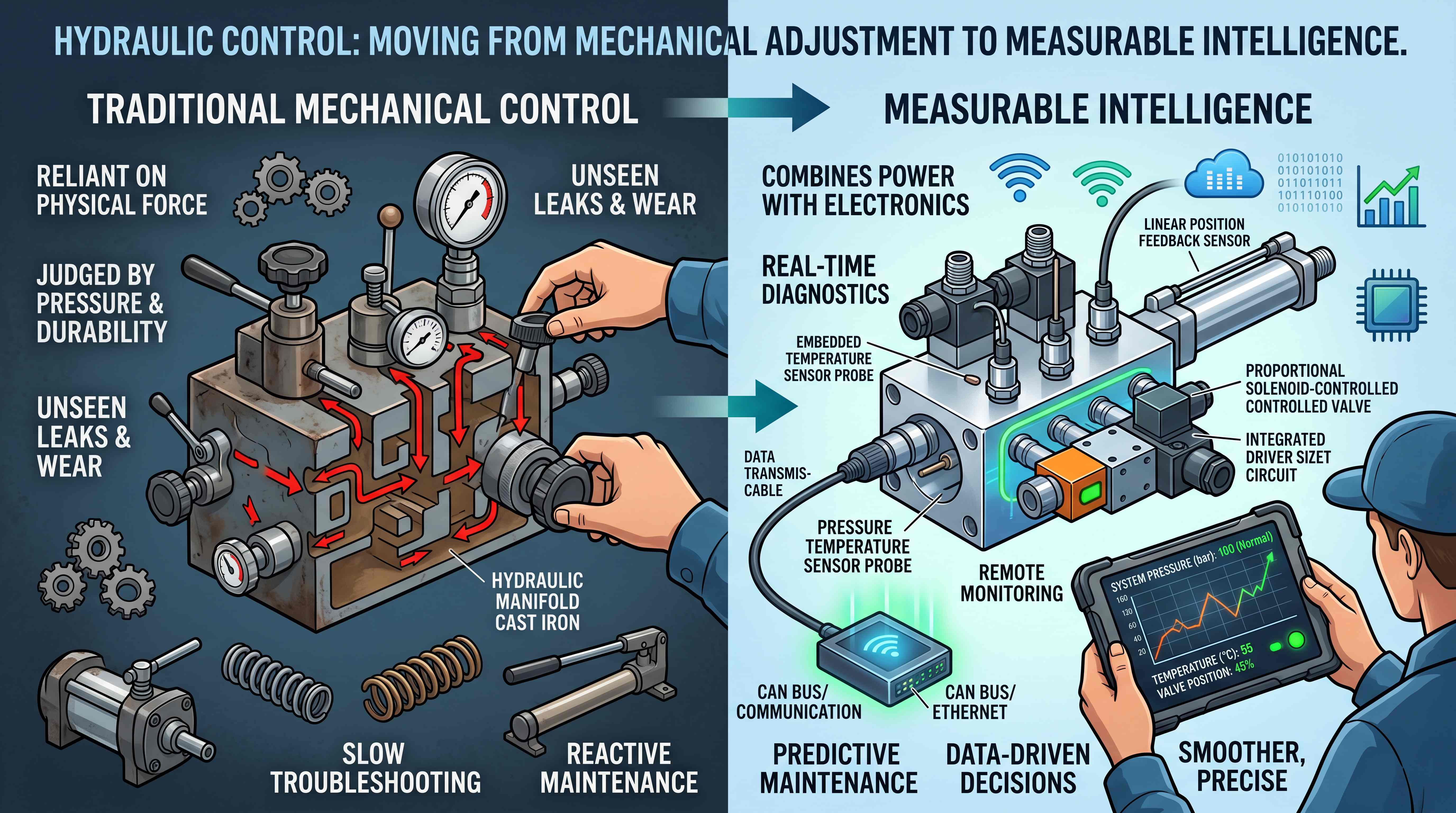
In older or simpler systems, hydraulic valves were often installed separately and connected with hoses or tubes. That approach still works in many applications, especially for repairs, prototypes and low-complexity machines. However, as machines become more compact, more automated and more function-rich, scattered valve arrangements can create problems. External plumbing takes space. Every fitting becomes a potential leak point. Hose routing becomes harder to repeat. Troubleshooting becomes slower. Production quality depends too much on manual assembly.
The modern hydraulic manifold function is to reduce that complexity.
A good manifold does not only make a hydraulic system look cleaner. It can improve reliability, reduce external connections, support repeatable OEM production, protect valves from exposed installation positions, and make the entire circuit easier to understand. In compact mobile equipment, industrial power units, agricultural machines, presses, lifts, marine systems and material handling equipment, manifold blocks are often the hidden reason why the hydraulic system feels organized rather than improvised.

The Problem With Too Many Hoses, Fittings and Separate Valves
To understand why hydraulic manifolds matter, start with the problems they solve.
A hydraulic circuit can be built from individual valves, pipe fittings, adapters, elbows, tees, hoses and tubes. For a very simple machine, this may be acceptable. But as the system grows, each additional connection adds complexity.
Every hose must be routed correctly. Every fitting must be tightened properly. Every threaded connection must seal under pressure. Every external line must be protected from vibration, abrasion, impact, heat and contamination. If the machine is built repeatedly in production, every unit must be assembled in the same way. If one technician routes a hose differently from another, service access, hose life and system appearance may vary.
Leakage risk also increases. A hydraulic leak may come from a damaged hose, loose fitting, poor sealing surface, cracked tube, incorrect thread combination or vibration fatigue. Even small leaks can create safety hazards, environmental concerns, oil loss, contamination, fire risk and customer dissatisfaction.
Complex external plumbing also makes troubleshooting harder. When a machine has many hoses crossing each other, it becomes difficult to trace oil flow. A technician may need to follow lines from the pump to the valve, from the valve to the cylinder, from the cylinder back to the tank, and through relief or check functions. If the circuit drawing does not match the real machine, diagnosis becomes even more difficult.
A hydraulic manifold block reduces these problems by moving part of the circuit inside a controlled, machined structure. Internal passages replace many external connections. Valves can be installed in predictable positions. Test points can be planned. Ports can be labeled. Hose routing can become shorter and cleaner.
This does not mean manifolds eliminate all problems. Poor hydraulic manifold design can create its own issues, such as pressure drop, heat generation, difficult access or confusing valve placement. But when designed correctly, a manifold turns a complicated hydraulic layout into a more integrated and repeatable control system.
The value is not only technical. It is also practical. A cleaner system can be assembled faster, inspected more easily, maintained with less confusion and presented more professionally to equipment buyers.
What a Hydraulic Manifold Block Actually Does

The basic hydraulic manifold function is to connect multiple hydraulic components through internal flow paths. The manifold may distribute pressure oil from the pump, return oil to the tank, direct oil to actuator ports, provide cavities for valves, hold sensors, include test ports and support multiple control functions in one body.
A typical manifold may include a pressure inlet marked P, a tank return marked T, actuator ports marked A and B, cartridge valve cavities, threaded plugs, gauge ports, pressure sensors, relief valve cavities, check valve cavities and mounting holes. Some manifolds are simple blocks with only a few ports. Others are complex integrated units with many valves and multiple actuator circuits.
In a directional control circuit, the manifold may route pressure oil to a directional valve and then to a cylinder. In a load-holding circuit, it may include check or counterbalance functions close to the actuator line. In a pressure control circuit, it may include a main relief valve or individual circuit relief valves. In a flow control circuit, it may contain adjustable or pressure-compensated flow control elements.
A manifold is sometimes described as a hydraulic traffic controller. That comparison is useful, but not complete. A manifold does not make control decisions by itself. The valves provide the active control functions. The manifold provides the physical pathways that allow those valve functions to work together.
A better way to understand it is this: a hydraulic schematic shows the circuit logic on paper, while the manifold block turns that logic into a compact physical component.
This is why manifold design should follow the circuit. The designer must understand pressure paths, return paths, actuator movement, load conditions, relief settings, valve interaction and service requirements before deciding where holes, cavities and ports should be placed. If the circuit is not understood, the manifold may be compact but unreliable.
A well-designed hydraulic valve manifold gives structure to the whole system. It makes the circuit easier to manufacture, easier to repeat and easier to service.
From External Plumbing to Integrated Hydraulic Circuits

One of the most important trends in hydraulic equipment is the move from separate plumbing toward the integrated hydraulic circuit.
An integrated hydraulic circuit combines multiple valve functions inside a manifold assembly. Instead of mounting a relief valve here, a check valve there, a flow control valve elsewhere and connecting everything with hoses, engineers integrate these functions into one valve block. This approach is especially common when using cartridge valves.
An integrated circuit can reduce the number of external hoses and fittings. It can shorten oil paths. It can place related functions close to each other. It can reduce the space needed for installation. It can make the machine easier to reproduce in production. It can also protect sensitive valve elements from exposed or awkward mounting locations.
This approach is very useful in mobile machinery. Compact loaders, agricultural attachments, construction equipment, lifting platforms and material handling machines often have limited space. A manifold allows several hydraulic functions to be installed in one area instead of spreading components around the machine.
It is also useful in industrial hydraulic power units. A power unit may need pressure relief, unloading, sequencing, flow control, pressure sensing and directional control. A manifold can organize these functions into a clean and serviceable layout.
For OEM manufacturers, integrated circuits support repeatability. Once a custom hydraulic manifold is validated, the same block can be used across multiple units. Production workers do not need to assemble many separate fittings in the same way each time. Quality control becomes more standardized. Service documentation can be built around one manifold assembly.
However, integration should not be confused with over-complication. A manifold should simplify the system, not hide problems inside a block. The best integrated hydraulic circuit is clear in function, logical in layout and supported by accurate documentation.
Main Hydraulic Manifold Types
There are several hydraulic manifold types, and each one fits a different system requirement. Understanding these types helps buyers and engineers avoid treating every manifold block as the same product.
A simple line manifold is used to connect or distribute flow between ports. It may serve as a junction block, reducing the need for tees and external fittings. These manifolds are often straightforward but still useful for cleaner installation.
A valve mounting manifold provides a base for one or more hydraulic valves. It may support subplate-mounted directional valves, CETOP or NFPA pattern valves, or other standardized valve interfaces. These manifolds are common in industrial systems where modular valve mounting is required.
A cartridge valve manifold contains cavities for screw-in or slip-in cartridge valves. This is one of the most important manifold types in modern hydraulic systems because cartridge valves allow pressure, flow, check, directional and load-holding functions to be integrated into a compact block.
A sandwich manifold is used between valve sections or between a valve and a mounting surface. It adds specific functions such as pressure reduction, flow control or check control without completely redesigning the whole valve stack.
A custom manifold is designed for a specific machine, circuit or OEM requirement. A custom hydraulic manifold may combine several functions, match a restricted installation space, align with hose routing, support sensors, reduce external connections and optimize machine assembly.
A modular manifold system uses standardized sections or stackable components. This approach can be useful when equipment families require similar but slightly different hydraulic functions.
A high-pressure manifold is designed for demanding pressure conditions and may require steel or ductile iron material, careful stress analysis and robust sealing design.
A low-pressure or moderate-pressure aluminum manifold may be suitable for compact equipment, hydraulic power units or applications where weight reduction and machining efficiency are important.
These categories often overlap. For example, a custom manifold may also be a cartridge valve manifold. A valve mounting manifold may include integrated relief or check functions. The important point is to identify the system purpose before choosing the manifold type.
Cartridge Valve Manifolds and Modular Control
The cartridge valve manifold is one of the strongest examples of modern hydraulic integration. Cartridge valves are compact valve elements that fit into machined cavities inside the manifold block. Depending on the design, they can perform relief, check, flow control, pressure reducing, sequence, counterbalance or directional functions.
This modular approach gives designers flexibility. Instead of building a system with many separate inline valve bodies, the designer can place multiple cartridge valves into one manifold. The block provides the internal passages, and the cartridge valves provide the control logic.
A cartridge valve manifold is especially useful when space is limited. It can also reduce leak points because fewer external fittings are needed. For equipment manufacturers, it can make the hydraulic system more repeatable. Once the manifold is designed, tested and documented, it becomes a stable control module.
Another advantage is service modularity. If a cartridge valve needs to be replaced, the technician may remove the cartridge from its cavity without replacing the whole manifold. If the system uses standard cavity designs, sourcing and replacement can be easier.
But cartridge valve manifolds require disciplined engineering. The cavity must match the cartridge valve specification. The flow rating must be appropriate. The valve function must match the circuit. Internal pressure drop must be considered. Seal material must be compatible with the fluid and temperature. The manifold must be labeled so technicians know which cartridge performs which function.
The biggest risk is assuming cartridge valves are universal. They are not. A cartridge valve can look similar to another but have different cracking pressure, spool behavior, flow capacity or pilot ratio. Installing the wrong cartridge can change the circuit behavior dramatically.
A good hydraulic manifold design makes cartridge valve functions visible through documentation, labeling and logical layout. The goal is integration without confusion.
Materials Used in Hydraulic Manifold Blocks
Choosing the right hydraulic manifold material is a practical engineering decision. The material affects pressure capability, weight, corrosion resistance, machining cost, durability and application suitability.
Aluminum is commonly used for many moderate-pressure applications. It is lightweight, easy to machine and suitable for compact hydraulic power units, mobile equipment and systems where weight matters. Aluminum manifolds can be cost-effective and efficient when pressure levels are within the material’s capability.
Steel is used when higher pressure, stronger thread strength or greater durability is required. Steel manifolds are common in demanding industrial and mobile applications where pressure spikes, shock loads or harsh conditions are expected. Steel is heavier and may require more machining effort, but it provides higher strength.
Ductile iron can also be used for high-pressure or demanding applications. It offers good strength and durability and may be suitable for certain industrial hydraulic systems.
Stainless steel may be used in corrosive environments, marine applications, food-related equipment or specialized systems where corrosion resistance is essential. It is typically more expensive but can be necessary when the environment demands it.
Material selection should not be based only on pressure rating. Other factors matter too: port thread strength, sealing method, fluid compatibility, surface treatment, operating temperature, machine vibration, exposure to moisture, and whether the manifold will be installed indoors or outdoors.
For a custom hydraulic manifold, material selection should be part of the design conversation from the beginning. A lightweight aluminum block may be attractive, but not if the application involves severe pressure spikes or harsh field operation. A steel block may be strong, but not ideal if weight is critical and pressure is moderate.
The correct material supports both hydraulic performance and machine economics.
What Good Hydraulic Manifold Design Must Consider
A strong hydraulic manifold design is not created by drilling holes into a block after choosing a few valves. It requires careful thinking about circuit logic, flow path efficiency, assembly, maintenance and manufacturability.
The first consideration is the hydraulic schematic. The schematic defines how pressure, flow and direction should be controlled. The manifold should reflect that logic. If the schematic is unclear, the manifold design will also be unclear.
The second consideration is flow capacity. Internal passages must be large enough to handle the required flow without excessive pressure drop. If passages are too restrictive, the system may generate heat, lose efficiency or respond poorly.
The third consideration is pressure rating. The block material, wall thickness, port design and drilled intersections must withstand working pressure and pressure spikes. High-pressure circuits require careful attention to stress concentration and sealing.
The fourth consideration is valve placement. Valves should be positioned logically. Components that require adjustment, testing or replacement should be accessible. Hidden or poorly oriented valves can create service problems.
The fifth consideration is port orientation. Hose connections should support clean routing. Good port placement reduces hose length, avoids sharp bends and improves machine assembly. Poor port placement can force awkward hose routing even if the manifold itself is compact.
The sixth consideration is sealing. O-rings, plugs, threaded ports and valve cavities must be designed to prevent internal and external leakage. Surface finish and machining accuracy matter.
The seventh consideration is contamination control. The manifold should be cleaned carefully after machining. Chips, burrs or debris inside internal passages can damage valves and actuators. This is a major quality issue in manifold manufacturing.
The eighth consideration is documentation. A manifold should have drawings, port labels, valve cavity information, torque requirements, test points and replacement part references. Without documentation, even a good block can become difficult to maintain.
Good manifold design is a balance between hydraulic performance, machine layout, manufacturing quality and service reality.
Standard Hydraulic Manifold or Custom Hydraulic Manifold?
One of the most important decisions is whether to use a standard manifold or a custom hydraulic manifold.
A standard manifold is suitable when the circuit requirement is common and does not need special layout. Standard products may reduce engineering time, shorten delivery and lower initial cost. They are useful for basic systems, common valve patterns and simple hydraulic power units.
A custom manifold is designed for a specific machine or application. It becomes valuable when the machine has limited space, special port orientation, multiple integrated valve functions, unique actuator logic, repeated production requirements or a need to reduce external hoses.
For OEMs, custom manifolds often make sense when production volume justifies the design effort. A custom block can improve assembly speed, reduce leak points, create a cleaner machine layout and support consistent quality across units.
For one-off repairs, a custom manifold may not always be economical. If the system can be fixed with standard valves and fittings, custom design may be unnecessary. But if the existing system is unreliable, difficult to service or too complex, a custom manifold may solve long-term problems.
The decision should not be based only on part price. A standard solution may be cheaper upfront but require more hoses, fittings, labor and service time. A custom solution may cost more initially but reduce total system cost over the machine lifecycle.
The best approach is to compare total value: component cost, assembly labor, leak risk, installation space, maintenance access, repeatability and downtime.
How Hydraulic Manifold Blocks Improve Serviceability
A well-designed hydraulic manifold block can make maintenance easier, but only if serviceability is built into the design.
Clear port labels help technicians identify pressure, tank and actuator lines. Accessible test ports allow pressure readings without disconnecting hoses. Logical valve placement helps technicians understand which valve controls which function. Replacement cartridges or adjustment points should be reachable without removing major machine structures.
Serviceability also depends on documentation. A manifold should be supported by a hydraulic schematic, bill of materials, valve cavity map, torque values, seal information and adjustment instructions. Without this information, technicians may waste time guessing.
A manifold can also reduce troubleshooting time because the circuit is centralized. Instead of tracing hoses across the machine, the technician can inspect a known control block. Pressure readings can be taken at planned points. Valves can be tested or replaced more systematically.
However, a poorly designed manifold can make service worse. If valves are hidden, labels are missing, test points are absent, or internal functions are not documented, troubleshooting becomes difficult. Technicians may not know whether a problem is caused by a relief valve, check valve, cartridge valve, blocked passage or external actuator issue.
This is why hydraulic manifold troubleshooting should be considered during design, not only after a failure occurs. The designer should ask: How will someone diagnose this system in two years? Can they identify each valve? Can they test pressure safely? Can they replace a cartridge without removing the entire assembly? Can they understand the circuit from the documentation?
A manifold that is easy to service creates value long after the machine leaves the factory.
Common Hydraulic Manifold Problems and Troubleshooting Clues
Even well-designed manifolds can experience problems if the system is contaminated, assembled incorrectly, overloaded or poorly maintained. Understanding common hydraulic manifold troubleshooting clues can help identify issues faster.
External leakage may appear around plugs, fittings, valve cavities, O-rings or port connections. Causes may include damaged seals, incorrect torque, surface damage, incompatible seal material, vibration or pressure spikes.
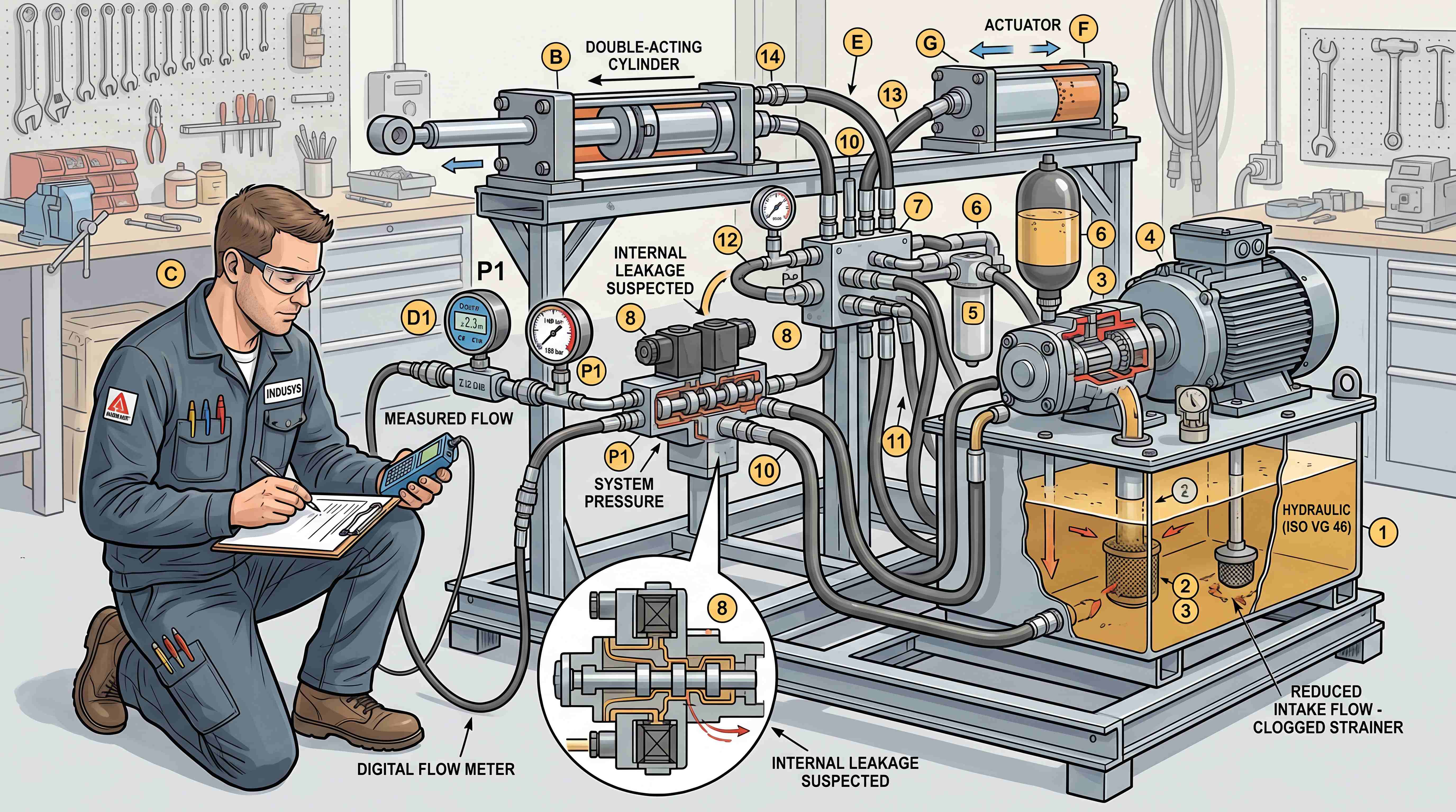
Internal leakage is harder to see. It may cause cylinder drift, weak holding force, slow movement or pressure loss. Internal leakage may come from worn valves, damaged cartridge seals, cracked internal passages or incorrect valve installation.
Blocked passages can cause actuators to move slowly, fail to move or behave unpredictably. Blockage may result from machining debris, contamination, hose failure particles or seal fragments.
Incorrect valve installation can create serious problems. A cartridge valve installed in the wrong cavity may change the circuit function. A missing plug may allow oil to bypass a control path. A wrong relief setting may prevent pressure from building or expose the system to overload.
Pressure drop can occur if internal passages are undersized or if flow is higher than expected. Symptoms may include heat generation, slow actuator movement and poor system efficiency.
Air trapped in the circuit can cause noise, spongy movement and unstable response. Although air is not always caused by the manifold itself, the manifold layout and port orientation can influence bleeding and commissioning.
Contamination is one of the most common causes of valve and manifold-related problems. Small particles can hold valves open, damage seats, scratch spools or block small orifices. Proper filtration and clean assembly are essential.
A practical troubleshooting approach starts with symptoms. Is the actuator slow? Is pressure low? Is the system hot? Is there external leakage? Does the load drift? Does the valve fail to shift? Then the technician checks pressure, flow, valve function, electrical signals, contamination and mechanical condition.
The manifold is not always the root cause, but it is often the best place to investigate the hydraulic control logic.
Applications Where Hydraulic Manifolds Create Strong Value
Hydraulic manifolds are used in many industries because they solve real machine design problems.
In construction machinery, manifolds help control booms, buckets, stabilizers, steering, auxiliary circuits and attachments. Compact integration is valuable because machines must handle vibration, shock loads and limited space.
In agricultural equipment, manifolds can simplify control of implements, lifting arms, folding mechanisms and hydraulic drives. Serviceability and ruggedness are important because equipment often operates in dirty field conditions.
In forklifts and material handling equipment, manifolds support lift, tilt, side-shift and steering functions. Smooth movement and reliable load holding are important for safety and operator confidence.
In industrial presses, manifolds help manage pressure build-up, holding, decompression and return movement. Pressure control and repeatability are critical.
In hydraulic power units, manifolds organize relief valves, unloading valves, check valves, directional valves, pressure sensors and test points. A clean manifold layout can make the power unit easier to assemble and maintain.
In lifting platforms and access equipment, load control functions can be integrated into compact valve blocks. Safety-related functions such as check and counterbalance control may be part of the manifold system.
In marine and offshore equipment, manifolds can reduce exposed plumbing and support more organized hydraulic control, but material selection and corrosion protection become important.
In manufacturing automation, manifolds can support repeatable hydraulic motion in compact equipment. When combined with solenoid or proportional valves, they can connect hydraulic power with electronic control systems.
Across these applications, the value of the manifold is not simply that it saves space. It helps make hydraulic control more structured, repeatable and maintainable.
Why Manifold Quality Affects the Whole Hydraulic System
The quality of a hydraulic manifold affects more than the block itself. It affects the entire hydraulic system.
Machining accuracy matters because valve cavities, ports and sealing surfaces must meet required tolerances. If a cavity is incorrect, the cartridge valve may leak, stick or fail to seat properly. If a sealing surface is damaged, external leakage may occur.
Deburring and cleaning are critical. Internal burrs or metal chips can break loose and damage valves, pumps or actuators. A manifold may look clean externally while still containing contamination inside internal passages.
Pressure testing is important to verify that the manifold can handle operating conditions. A block should be tested for leakage, sealing and circuit correctness when required by the application.
Surface treatment may also matter. Corrosion protection, anodizing, plating or coating may be used depending on material and environment.
Assembly quality is equally important. Valves must be installed in the correct cavities. Seals must be correct. Plugs must be tightened properly. Adjustments must match system requirements. Labels must be accurate.
A low-quality manifold can cause problems that appear to be valve failures, pump failures or actuator issues. This is why buyers should evaluate not only price but also engineering capability, machining quality, cleaning process, documentation and testing.
In serious hydraulic applications, the manifold should be treated as a precision control component, not as a simple metal block.
The Future of Hydraulic Manifold Design
Hydraulic manifold design is evolving as machines become more compact, electronically controlled and service-data driven.
One trend is greater integration. More functions are being combined into compact valve blocks, especially through cartridge valve manifolds. This reduces external plumbing and supports cleaner machine architecture.
Another trend is closer connection with electronics. Manifolds increasingly include pressure sensors, temperature sensors, proportional valves and electrical connectors. The manifold becomes part of a wider electrohydraulic control system.
A third trend is design optimization. Engineers are paying more attention to pressure drop, flow path efficiency, heat generation and energy loss. A compact block is not enough; the internal flow must also be efficient.
A fourth trend is modularity. Equipment manufacturers want manifold platforms that can support multiple machine versions with minimal changes. A well-planned manifold family can help OEMs manage product variation.
A fifth trend is better service documentation. QR codes, digital manuals, valve maps and clearer labeling can help technicians understand manifold functions faster.
A sixth trend is manufacturability through advanced machining and digital design tools. CAD, simulation, CNC machining and improved inspection methods allow more complex manifolds to be produced with higher consistency.
These trends show that hydraulic manifolds are not old-fashioned components. They remain highly relevant as hydraulic systems become more integrated with modern machine design.
Conclusion: A Hydraulic Manifold Block Is a System Strategy
A hydraulic manifold block is not just a convenient way to connect hoses. It is a system strategy.
It brings valves, ports, internal channels, pressure control, flow paths, actuator connections and service points into one organized structure. It helps reduce external plumbing, lower leak risk, improve assembly repeatability and support compact machine design. When combined with cartridge valves, it can form an integrated hydraulic circuit that is more efficient and easier to package than a collection of scattered components.
But the value of a manifold depends on design quality. Good hydraulic manifold design starts from circuit logic, not from block shape. It considers pressure, flow, valve interaction, material, service access, port orientation, documentation and troubleshooting. A poor manifold can hide problems. A well-designed manifold makes the hydraulic system easier to build, operate and maintain.
For machine builders, a custom hydraulic manifold can improve production consistency and reduce lifecycle complexity. For maintenance teams, a clear manifold layout can shorten troubleshooting time. For equipment buyers, a well-integrated hydraulic valve manifold can indicate a more mature and professionally engineered machine.
In modern hydraulic systems, the manifold is where control logic, mechanical packaging and service reality meet. That is why hydraulic manifold blocks deserve more attention than they often receive. They are not simply blocks of metal. They are the physical architecture of hydraulic control.
#HydraulicValveManifold
#HydraulicManifoldDesign
#CustomHydraulicManifold
#HydraulicManifoldTypes
#IntegratedHydraulicCircuit
#CartridgeValveManifold
#HydraulicManifoldMaterial
#HydraulicSystemDesign
#IndustrialHydraulics
#MobileHydraulics
#FluidPower
#HydraulicTroubleshooting
#IndustrialComponents
#HydraulicEngineering