Cartridge Valves in Hydraulic Manifolds: Compact Control for Mobile and Industrial Equipment
Cartridge Valves Are Small Components With System-Level Influence
A hydraulic cartridge valve is easy to underestimate. Compared with a large directional control valve, a visible valve bank or a complete hydraulic power unit, a cartridge valve may look like a small threaded or inserted component. It may be installed deep inside a hydraulic manifold block, hidden behind a plug, coil, adjustment screw or valve cavity. But in modern hydraulic systems, cartridge valves often carry some of the most important control functions in the entire circuit.
A cartridge valve may control pressure, limit flow, block reverse movement, hold a load, regulate actuator speed, shift a hydraulic path, unload a pump or protect a machine from overload. Several cartridge valves installed in one manifold can work together as a complete hydraulic integrated circuit. In this sense, a cartridge valve is not just a spare part. It is a functional building block of hydraulic control.
The reason cartridge valves are so important is that modern machines need compact, repeatable and serviceable hydraulic systems. External hoses, inline valves and scattered fittings can still work, but they become harder to manage as machines become smaller, more automated and more complex. A cartridge valve manifold allows multiple functions to be integrated into one block. The manifold provides internal oil passages, while the cartridge valves provide the control logic.
This is especially valuable in mobile machinery, agricultural equipment, forklifts, industrial presses, lifting platforms, hydraulic power units and compact industrial machines. These applications often have limited installation space, strict reliability expectations and repeated production requirements. Cartridge valves help designers turn a complicated hydraulic schematic into a compact and organized control module.
However, cartridge valves are not automatically simple. Choosing the wrong valve, using the wrong cavity, ignoring pressure drop, overlooking contamination or misunderstanding pilot ratios can create serious performance problems. Good cartridge valve use requires both component knowledge and circuit thinking.
Why Cartridge Valves Became Important in Modern Hydraulic Systems

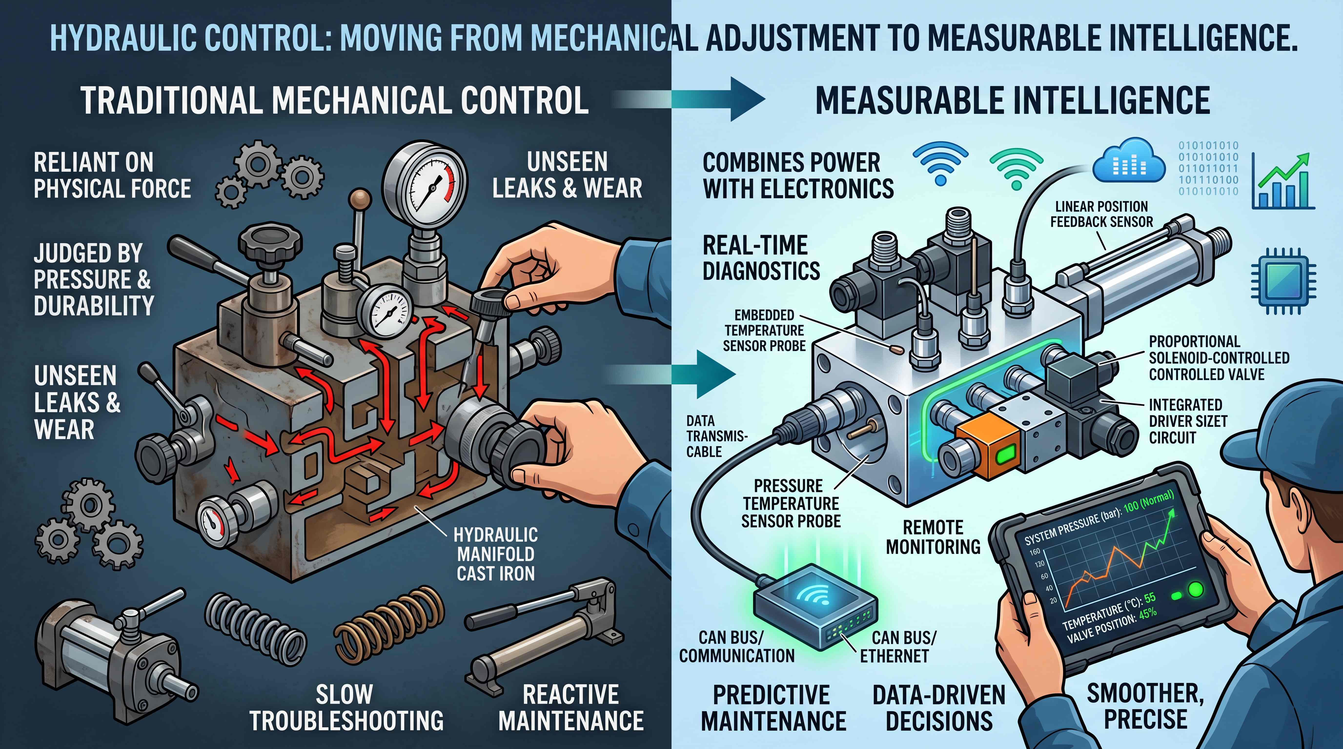
Traditional hydraulic systems often used separate valve bodies connected by hoses, pipes and fittings. This layout was understandable because each component could be seen and replaced individually. But when a machine required many functions, the system quickly became crowded. Hose routing became complicated. Leak points increased. Assembly consistency depended on workmanship. Troubleshooting required tracing lines across the machine.
Cartridge valves helped change that approach.
A cartridge valve is designed to fit into a prepared cavity. That cavity is usually machined into a hydraulic manifold block. The manifold contains the internal passages that connect the cartridge valve to pressure, tank, actuator or pilot lines. Instead of installing many separate valves externally, the designer can integrate them into a single block.
This brings several advantages.
First, the hydraulic system becomes more compact. A manifold with cartridge valves can contain pressure relief, flow control, check, directional and load-holding functions in a much smaller space than separate valve bodies.
Second, external leak points are reduced. Every hose connection is a potential leakage point. When flow paths move inside the block, there are fewer external fittings to seal.
Third, production becomes more repeatable. OEM manufacturers can install the same manifold assembly on every machine instead of relying on complex manual hose layouts.
Fourth, service can become more structured. If the manifold is labeled and documented properly, technicians can identify the function of each cartridge valve and replace it without rebuilding the entire circuit.
Fifth, the system becomes easier to package inside modern machinery. Compact machines cannot always afford long valve banks or exposed plumbing. Cartridge valve integration helps fit hydraulic control into restricted spaces.
The larger industry trend is clear: cartridge valves support the move from component-level hydraulics to system-level hydraulic integration. They help transform a collection of valves into a designed control architecture.
What Is a Hydraulic Cartridge Valve?

A hydraulic cartridge valve is a compact valve element installed into a cavity to perform a specific hydraulic function. It may be threaded into the cavity, inserted into a bore, held by a cover, or combined with a coil or adjustment mechanism depending on its design.
The valve itself may include a spool, poppet, spring, seat, sleeve, orifice, adjustment screw, seals and sometimes an electric coil. Its job depends on its internal design. Some cartridge valves open at a set pressure. Some regulate flow. Some block reverse flow. Some shift direction. Some respond to pilot pressure. Some operate electrically. Some provide proportional control.
The key difference between a cartridge valve and many traditional inline valves is packaging. A traditional valve body contains both the valve mechanism and the external flow ports. A cartridge valve usually relies on the manifold block for the external flow path. The cartridge provides the control function, while the manifold provides the housing and connection logic.
This is why a cartridge valve cannot be understood alone. It must be understood together with the cavity and manifold circuit. A cartridge valve installed in the wrong cavity or connected to the wrong internal passage may not perform the intended function. A technically correct valve can behave incorrectly if the manifold circuit is wrong.
For example, a pressure relief cartridge valve must be connected to the pressure line and relief path correctly. A flow control cartridge valve must be placed in the proper meter-in or meter-out position. A check valve cartridge must face the correct flow direction. A load-holding cartridge must be installed with correct pilot and actuator connections.
This is the core principle: a cartridge valve is a function, not just a shape. Its performance depends on the hydraulic circuit around it.
Screw-In Cartridge Valve: Compact and Widely Used

The screw-in cartridge valve is one of the most common cartridge valve formats in mobile and industrial hydraulic systems. As the name suggests, it threads into a machined cavity in the manifold block. It typically uses O-rings and backup rings to seal different pressure zones. Many screw-in cartridge valves can be removed and replaced from the outside of the manifold.
Screw-in cartridge valves are popular because they are compact, modular and flexible. A designer can use standard cavities for different valve functions. A manifold may include screw-in relief valves, check valves, flow control valves, pressure reducing valves, sequence valves, counterbalance valves and solenoid-operated valves.
This makes screw-in cartridge valves especially useful for OEM equipment. A machine manufacturer can design a manifold around a specific set of control functions. Once validated, that manifold can be produced repeatedly. If a function needs a different pressure setting or flow rating, the cartridge may sometimes be changed without completely redesigning the block.
Screw-in cartridge valves are also useful for maintenance. If a valve is damaged or contaminated, technicians may be able to remove the cartridge, inspect it, clean the cavity and install a replacement. This is more convenient than replacing a whole valve assembly.
However, screw-in cartridge valves require careful application. The cavity standard must match the valve. The seal arrangement must be correct. Torque must be applied properly. The manifold material must support the pressure and thread loading. Flow capacity must be sufficient. Pressure drop must be considered. Contamination must be controlled.
One common mistake is assuming two screw-in cartridge valves are interchangeable because they look similar. They may have different cavity requirements, seal positions, flow directions, pilot ratios, cracking pressures or internal functions. Substituting the wrong valve can change the circuit behavior and cause unsafe operation.
The screw-in cartridge valve is powerful because of its modularity, but that modularity only works when engineering control is disciplined.
Slip-In Cartridge Valve: High-Flow Control for Demanding Systems

The slip-in cartridge valve is another important cartridge valve type. It is often used in high-flow, high-pressure or demanding industrial hydraulic applications. Unlike many screw-in cartridge valves, a slip-in cartridge valve is typically inserted into a bore and retained by a cover or control cap. It may be used as a logic element in larger hydraulic circuits.
Slip-in cartridge valves are common in systems that require high flow capacity and fast response. They are often found in presses, large industrial machines, injection molding equipment, die casting systems, steel machinery and heavy-duty hydraulic power units.
A slip-in cartridge valve can act as a two-way logic element. With the right pilot control, it can perform directional, pressure or flow-related functions. Multiple slip-in cartridges can be arranged to create advanced hydraulic logic. This makes them suitable for powerful systems where conventional spool valves may be too restrictive or too large.
The advantage of a slip-in cartridge valve is performance. It can handle large flows with relatively low pressure drop when properly applied. It can also support advanced circuit design where pilot pressure controls main flow paths.
However, slip-in cartridge valves usually require more engineering experience. The designer must understand pilot control, area ratios, flow direction, pressure balance, response behavior and manifold machining accuracy. These valves are not usually selected casually from a simple parts list. They are part of a carefully engineered hydraulic circuit.
For many compact machines, screw-in cartridge valves are more common. For high-flow industrial systems, slip-in cartridge valves can be a more appropriate choice. The decision depends on the application, not on which format seems more advanced.
This is a useful industry distinction: screw-in cartridge valves are often associated with compact modular integration, while slip-in cartridge valves are often associated with high-flow hydraulic logic and demanding industrial performance.
How Cartridge Valves Work Inside a Hydraulic Manifold Block
A hydraulic manifold block gives cartridge valves their physical circuit. The block is drilled or machined with internal passages that connect pressure, tank, actuator and pilot lines. Cartridge valve cavities are placed at strategic points in these passages. When a cartridge valve opens, closes, shifts or modulates, it changes how oil moves through the internal circuit.
Imagine a manifold controlling a hydraulic cylinder. The manifold may have a pressure inlet, a tank return, actuator ports A and B, and several cartridge valve cavities. A directional cartridge valve may determine whether pressure oil goes to port A or port B. A check valve cartridge may prevent reverse flow. A pressure relief cartridge valve may protect the circuit if pressure rises too high. A flow control cartridge valve may regulate cylinder speed. A counterbalance cartridge valve may control lowering under load.
Together, these valves form a hydraulic integrated circuit.
The manifold is not just a container. It defines the connection logic. If a passage is too small, pressure drop may increase. If a drilled intersection is poorly placed, flow may become inefficient. If service ports are missing, troubleshooting becomes harder. If cartridge positions are not labeled, maintenance becomes risky.
The quality of the hydraulic manifold block directly affects cartridge valve performance. A good cartridge valve cannot overcome a poorly designed manifold. Burrs, machining debris, wrong cavity dimensions, damaged seal surfaces or incorrect passage connections can all cause problems.
This is why professional cartridge valve manifold design must consider both the valve and the block as one system. The valve provides control, and the manifold provides hydraulic context. They must be engineered together.
Common Cartridge Valve Functions in Manifold Systems

Cartridge valves can perform many functions. Understanding these functions is essential for cartridge valve selection.
A pressure relief cartridge valve protects the hydraulic system from excessive pressure. When pressure reaches the set value, the valve opens and allows oil to flow to tank or another low-pressure path. This protects pumps, hoses, actuators, seals and structural components from overload.
A pressure reducing cartridge valve maintains a lower pressure in a branch circuit. This is useful when one part of the machine needs less pressure than the main system.
A sequence cartridge valve allows one actuator or circuit to operate after another reaches a set pressure. This is common in clamping, pressing or staged machine movements.
A flow control cartridge valve regulates oil flow to control actuator speed. It may be adjustable, pressure compensated or combined with check valve behavior for free reverse flow.
A check cartridge valve allows flow in one direction and blocks reverse flow. It is used for circuit isolation, load holding, pump protection and return-flow control.
A pilot-operated check cartridge valve blocks reverse flow until pilot pressure opens it. It can be useful for holding a cylinder position, although it must not be confused with a counterbalance valve when controlled lowering is needed.
A counterbalance cartridge valve controls overrunning loads. It helps prevent uncontrolled descent in lifting arms, platforms, booms and vertical cylinders.
A directional cartridge valve controls the path of oil flow. It may be a simple two-way or three-way cartridge, or part of a more complex directional function inside a manifold.
A solenoid cartridge valve uses an electric coil to open, close or shift a hydraulic path. These valves are common in compact manifold systems where electrical control is needed.
A proportional cartridge valve allows variable control based on an electrical input. It can support smoother motion, adjustable speed or pressure modulation.
These cartridge valve functions show why manifold systems can be so compact. Instead of using large separate valve bodies for each task, the designer can integrate several cartridge functions into one block.
Directional Cartridge Valves and Oil Path Control
A directional cartridge valve controls where hydraulic oil goes inside a manifold circuit. It may open or close a flow path, switch between pressure and tank, or direct oil toward an actuator line. Directional cartridge valves may be mechanically operated, pilot-operated or solenoid-operated depending on the system.
In simple circuits, a directional cartridge may act as an on/off valve. When energized or piloted, it allows oil to pass. When not actuated, it blocks the path. In more complex circuits, multiple directional cartridges may work together to provide extend, retract, neutral, unload or regeneration functions.
Directional cartridge valves are often used where compactness is more important than having a traditional spool valve body. They can be integrated into a manifold close to other functions such as relief, check and flow control. This reduces external piping and helps create a cleaner circuit layout.
However, directional cartridge valves must be selected carefully. The designer must understand normally open or normally closed behavior, flow direction, pressure rating, leakage characteristics, response time and actuation method. In solenoid versions, coil voltage and duty cycle also matter.
A directional valve error can be serious because it changes actuator movement. If the valve is normally open instead of normally closed, the machine may behave unexpectedly. If flow direction is wrong, the valve may not seal or shift properly. If the valve is undersized, pressure drop and heat may increase.
For this reason, directional cartridge valves should always be evaluated within the full hydraulic schematic. They are not just electric shutoff elements. They are part of the machine’s movement logic.
Pressure Relief Cartridge Valves and Circuit Protection
A pressure relief cartridge valve is commonly installed in a manifold to protect a system or branch circuit from excessive pressure. It opens when pressure rises above a set level, allowing oil to escape to tank or a lower-pressure line.
In many systems, the main relief function is located near the pressure inlet of the manifold. Additional circuit relief cartridges may be installed on actuator lines to protect individual sections of the machine. For example, a cylinder circuit may need port relief valves to handle shock loads or external force.
Pressure relief cartridge valves are valuable because they allow pressure protection to be placed close to the relevant circuit. This can improve packaging and reduce the need for separate external relief valve bodies.
But relief valves must be applied correctly. A relief valve set too low can make the machine weak. A relief valve set too high can expose components to dangerous pressure. A contaminated relief valve may stick open and prevent pressure from building. A stuck closed valve may remove system protection. If a machine continuously operates over the relief valve, oil temperature can rise and efficiency can fall.
In a cartridge valve manifold, relief cartridges should be accessible for adjustment and service. Their function should be clearly labeled. The setting should be documented. If different circuits use different relief settings, the manifold should make this clear to avoid maintenance errors.
Pressure relief is one of the most important safety and reliability functions in hydraulic systems. A pressure relief cartridge valve may be small, but it defines the pressure boundary of the circuit.
Flow Control Cartridge Valves and Actuator Speed
A flow control cartridge valve regulates how much oil passes through part of a hydraulic circuit. Since actuator speed depends on flow, this cartridge valve type is used to control cylinder movement, hydraulic motor speed or controlled lowering.
In a manifold system, a flow control cartridge may be used for meter-in or meter-out control. Meter-in control regulates flow entering the actuator. Meter-out control regulates flow leaving the actuator. The correct approach depends on whether the load is resisting movement or helping drive movement.
For example, when lowering a vertical load, meter-out control may be important because gravity can pull the load down faster than the pump supplies oil. In this case, controlling outlet flow helps prevent runaway movement. In other cases, meter-in control may be suitable when load conditions are stable.
Some flow control cartridge valves are simple adjustable restrictors. Others are pressure compensated, meaning they maintain more stable flow even when load pressure changes. Some include a reverse free-flow check function so oil can flow freely in one direction while being controlled in the other.
Flow control cartridges can improve machine feel, process quality and safety. A cylinder that moves too fast may shock the structure. A cylinder that moves too slowly may reduce productivity. A cylinder that changes speed under load may create inconsistent operation.
However, flow control through restriction creates pressure drop. Pressure drop creates heat. If a flow control valve is used to waste large amounts of energy continuously, the system may overheat. This is why flow control cartridge selection must consider flow rate, pressure drop, duty cycle and heat management.
A flow control cartridge should not be added blindly to “slow something down.” It should be part of a complete hydraulic design that considers energy, load behavior and actuator control.
Cartridge Valve Selection Starts With the Circuit

Good cartridge valve selection begins with the hydraulic circuit, not the catalog page.
The first question is function. What does the valve need to do? Does it limit pressure, control speed, block reverse flow, hold a load, shift direction or unload a pump? A cartridge valve must match the control task.
The second question is pressure. What is the normal working pressure? What pressure spikes may occur? Does the valve need to protect against shock loads? The pressure rating must be suitable for real conditions, not just nominal pressure.
The third question is flow. How much oil must pass through the valve? What pressure drop is acceptable? A valve that is too small may create heat and slow actuator response. A valve that is too large may reduce controllability or increase cost.
The fourth question is flow direction. Cartridge valves often have specific flow direction requirements. Installing the valve in the wrong orientation or using it in the wrong path can cause leakage, instability or failure.
The fifth question is cavity compatibility. The cartridge valve must match the manifold cavity. Thread, diameter, seal positions, depth and port connections must be correct.
The sixth question is actuation method. Is the valve direct-acting, pilot-operated, solenoid-operated or proportional? Does the system have the correct pilot pressure or electrical control?
The seventh question is adjustment and service. Does the valve require field adjustment? Will technicians be able to access it? Is the setting documented?
The eighth question is fluid cleanliness. Cartridge valves can be sensitive to contamination. Proper filtration and clean assembly are essential.
The ninth question is environment. Temperature, vibration, moisture, dust and corrosion can affect coils, seals, threads and adjustment mechanisms.
The final question is system interaction. A cartridge valve does not operate alone. It interacts with pumps, actuators, other valves, sensors and control logic. A correct cartridge in the wrong system can still perform poorly.
Why Cartridge Valve Manifolds Support OEM Machine Design
A cartridge valve manifold is especially valuable for OEM manufacturers because it helps turn hydraulic control into a repeatable module.
In one-off equipment, external valves and hoses may be acceptable. But in repeat production, consistency becomes critical. Every machine must perform the same way. Every hose route must be controlled. Every pressure setting must be repeatable. Every service technician must be able to understand the system.
A cartridge valve manifold helps by centralizing hydraulic functions. The manifold can be designed, tested and documented as one assembly. Production workers can install the complete manifold rather than building a complex network of separate valves. Quality inspection becomes easier. The machine layout becomes cleaner.
For OEMs, this can reduce assembly time, lower leakage risk and improve service documentation. It can also support product variation. One equipment platform may use similar manifold architecture with different cartridge combinations for different functions or models.
A well-designed manifold can also support supply chain efficiency. Instead of purchasing and managing many separate valve bodies, fittings and adapters, the OEM may manage a smaller number of manifold assemblies and cartridge valve options.
However, OEM benefits depend on good engineering. If the manifold is poorly designed, difficult to service or too specialized, it can become a bottleneck. The best manifold strategy balances integration with maintainability.
The goal is not to hide the hydraulic system inside a block. The goal is to make the hydraulic system more controlled, more repeatable and easier to support over the life of the machine.
Common Problems in Cartridge Valve Applications
Cartridge valve systems can fail or perform poorly for several reasons. Many problems are not caused by the cartridge valve alone, but by the interaction between valve, manifold, fluid and application.
Contamination is one of the most common issues. Dirt, metal particles, seal fragments or varnish can hold a valve open, block an orifice, damage a seat or cause a spool to stick. Clean oil and proper filtration are essential.
Wrong valve installation is another common problem. A cartridge may be placed in the wrong cavity, installed with damaged seals, tightened incorrectly or replaced with a similar-looking but incorrect model.
Incorrect settings can also create problems. A relief valve set too low may reduce machine force. A counterbalance valve set too high may cause heat and unstable motion. A flow control valve adjusted too restrictively may slow the machine and increase pressure drop.
Cavity damage can cause leakage or poor valve operation. Scratched sealing surfaces, burrs, incorrect machining or debris inside the cavity can prevent proper sealing.
Electrical faults affect solenoid cartridge valves. Low voltage, incorrect coil, damaged connector, moisture ingress or overheated coils can stop the valve from shifting. A hydraulic problem may appear electrical, or an electrical problem may appear hydraulic.
Pilot pressure problems can affect pilot-operated cartridge valves. If pilot pressure is too low, unstable or incorrectly connected, the valve may not open or close as expected.
Pressure drop and heat can occur when the cartridge is undersized or when the internal manifold passages are too restrictive. This may not be obvious from visual inspection.
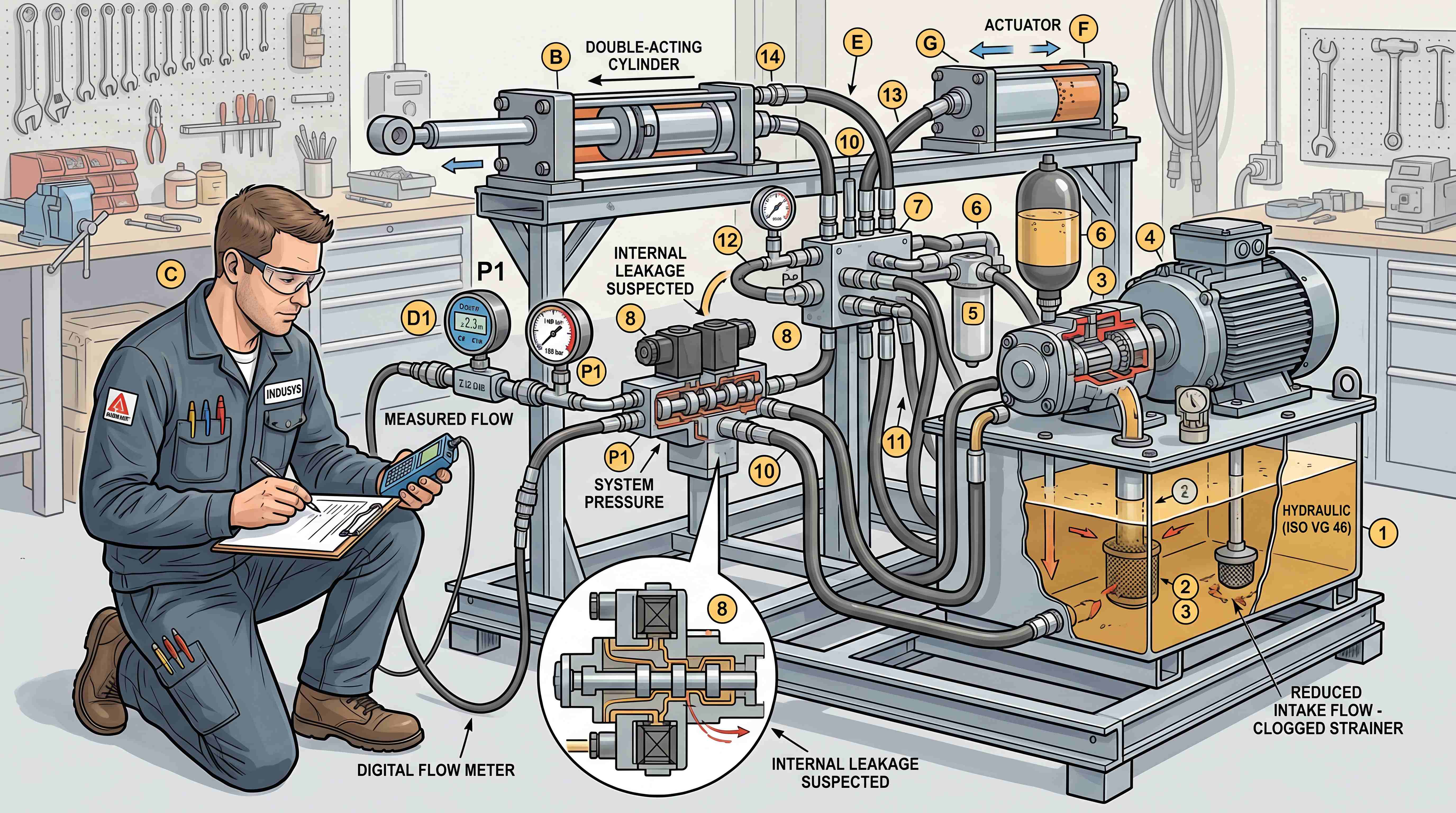
These issues show why cartridge valve troubleshooting should follow a structured process: check symptoms, verify pressure, inspect electrical signals, confirm valve function, review the schematic, check cleanliness, inspect the cavity and confirm correct replacement parts.
Maintenance and Documentation Matter as Much as Design
A cartridge valve system is only as serviceable as its documentation.
A manifold should clearly identify every cartridge valve. Technicians should know which valve controls pressure relief, which one controls flow, which one blocks reverse flow and which one operates a directional function. Port labels, cavity maps, hydraulic schematics and bill of materials are essential.
Torque values should be available. Seal kits should be identified. Adjustment settings should be recorded. Coil voltages should be marked. If multiple valves look similar, the documentation should prevent accidental interchange.
Cleanliness during maintenance is critical. When a cartridge valve is removed, the open cavity must be protected from dirt. Seals should be inspected. The cavity should be checked for damage. The replacement valve should be confirmed before installation. After service, the system should be tested carefully.
For machines working in harsh environments, connectors and coils need attention. Moisture, vibration and contamination can damage electrical components. Protective connectors and proper cable routing help reduce failure risk.
Cartridge valve maintenance should not be treated as casual part swapping. Because cartridge valves are embedded in circuit logic, replacing the wrong component can change system behavior. Professional maintenance protects both performance and safety.
Where Cartridge Valves Create the Most Value
Cartridge valves create strong value where compact control, repeatability and integrated design matter.
In mobile equipment, cartridge valve manifolds can reduce hose routing and fit multiple functions into restricted spaces. Loaders, compact construction machines, aerial platforms and utility vehicles often benefit from this approach.
In agricultural machinery, cartridge valves support durable and compact implement control. Machines operating in dirty field environments need reliable valve functions and serviceable manifold layouts.
In material handling equipment, cartridge valves can control lift, tilt, side shift, steering and load-holding functions. Smooth and safe movement is important when handling loads.
In industrial presses, cartridge valves can manage pressure relief, decompression, sequence control, check functions and flow control. High force and repeatability are major requirements.
In hydraulic power units, cartridge valve manifolds can organize relief, unloading, directional, check and pressure-sensing functions into a clean assembly.
In lifting platforms, counterbalance and check cartridge valves can support load holding and controlled lowering when properly applied.
In marine and heavy-duty industrial systems, cartridge valves can reduce external plumbing and support more protected installation, although material selection and corrosion resistance become important.
Across these applications, the value is not simply that cartridge valves are small. Their real value is that they make hydraulic control more modular, integrated and adaptable.
Conclusion: Cartridge Valves Are the Modular Logic of Hydraulic Manifolds
A hydraulic cartridge valve may be small, but its role in modern hydraulic systems is significant. It can control pressure, flow, direction, reverse flow, load holding and electrical actuation inside a compact manifold assembly.
When installed in a hydraulic manifold block, cartridge valves help create a hydraulic integrated circuit. The manifold provides internal flow paths, while the cartridge valves provide control functions. This combination reduces external plumbing, lowers leak-point count, improves OEM repeatability and supports compact machine design.
A screw-in cartridge valve is widely used for compact and modular applications. A slip-in cartridge valve is often used for demanding high-flow industrial circuits. A directional cartridge valve controls oil path logic. A pressure relief cartridge valve protects the system. A flow control cartridge valve regulates actuator speed. Together, these components allow engineers to build sophisticated hydraulic control into a compact block.
But cartridge valves require careful application. Correct cartridge valve selection must consider function, pressure, flow, cavity compatibility, actuation method, cleanliness, service access and system interaction. A cartridge valve is never just an isolated component. It belongs to a circuit.
For machine builders, cartridge valve manifolds can improve packaging and production consistency. For maintenance teams, proper documentation and clean service practices are essential. For buyers, a well-designed cartridge valve manifold can indicate a more mature hydraulic system.
The real lesson is simple: cartridge valves are not just small valves placed inside a block. They are modular control elements that help modern hydraulic systems become more compact, repeatable, serviceable and intelligent.
#HydraulicCartridgeValve
#CartridgeValveManifold
#ScrewInCartridgeValve
#SlipInCartridgeValve
#HydraulicManifoldBlock
#HydraulicIntegratedCircuit
#DirectionalCartridgeValve
#PressureReliefCartridgeValve
#FlowControlCartridgeValve
#CartridgeValveSelection
#HydraulicValves
#HydraulicManifolds
#IndustrialHydraulics
#MobileHydraulics
#FluidPower