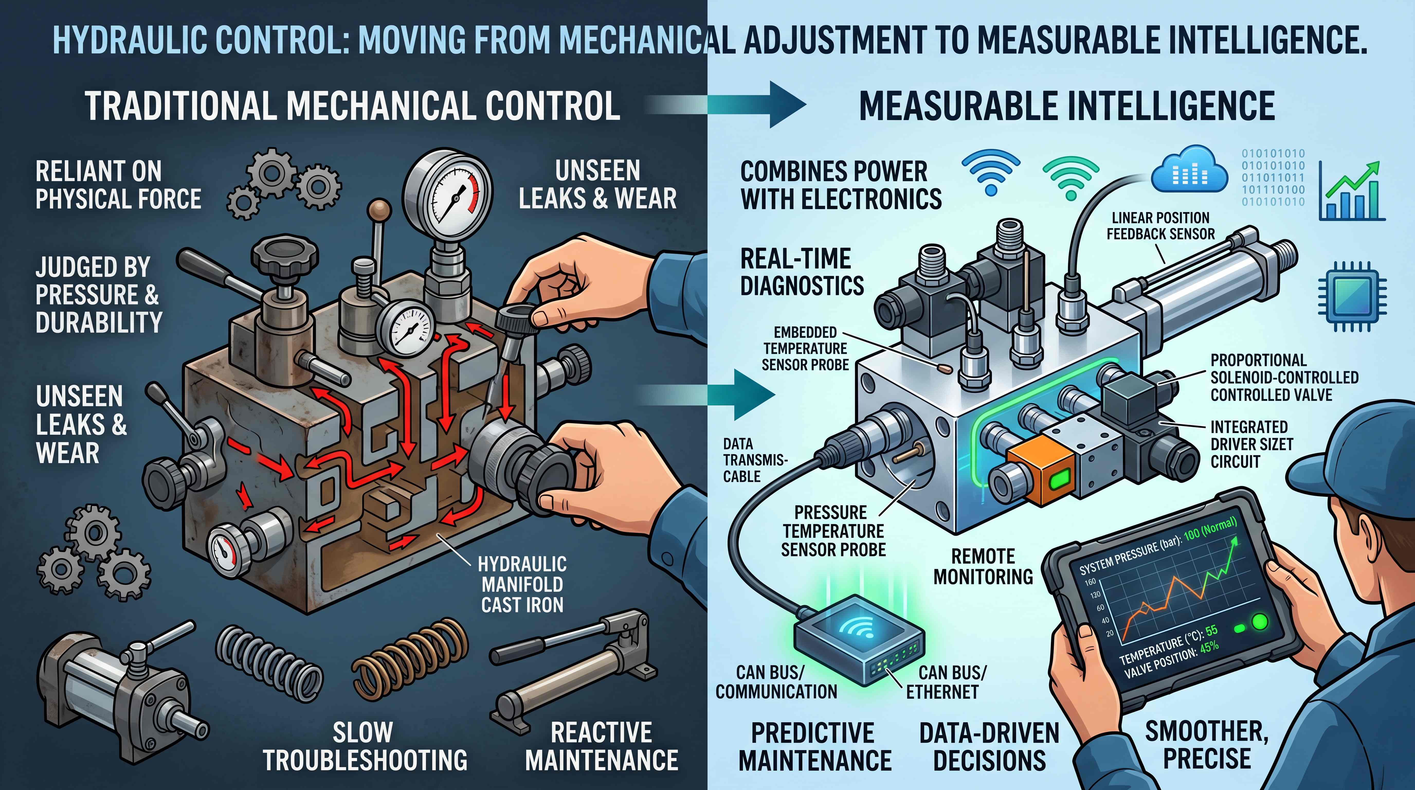
How to Choose Hydraulic Valves and Manifolds for Your Application
Choosing Hydraulic Valves and Manifolds Starts With the Machine, Not the Catalog
Choosing hydraulic components often looks simple from the outside. A buyer may open a product catalog, search for a pressure rating, compare port sizes, check the price and place an order. But in real hydraulic systems, this shortcut can create expensive problems.
A valve with the right thread size may still be wrong for the circuit. A manifold with enough ports may still create poor hose routing. A component with a high pressure rating may still cause excessive heat if the flow capacity is too small. A solenoid valve may look suitable, but fail to shift reliably if voltage, duty cycle or contamination conditions are ignored. A compact manifold may reduce space, but make maintenance difficult if test ports and cartridge locations are not planned.
This is why hydraulic valve selection and hydraulic manifold selection should always begin with the machine application, not the catalog page.
The purpose of a hydraulic valve is to control pressure, flow, direction, load holding, unloading, sequencing or actuator motion. The purpose of a hydraulic manifold is to organize those control functions into a compact, repeatable and serviceable structure. These two decisions are connected. You do not truly choose hydraulic valves without understanding the circuit, and you do not truly choose hydraulic manifold solutions without understanding how the valves, ports, hoses, actuators and service points must work together.
A good selection process asks practical questions first. What does the machine need to do? What actuator is being controlled? What pressure is required? What flow rate is needed? Is the load stable or overrunning? Does the system need manual, solenoid, pilot or proportional control? Is the equipment built once, repaired in the field or manufactured repeatedly by an OEM? Does the application require a standard valve block or a custom hydraulic manifold?
The answers to these questions turn valve and manifold selection from guesswork into engineering judgment.

Define the Hydraulic System Requirements Before Selecting Components
Every strong selection process starts with clear hydraulic system requirements. Without this foundation, component selection becomes a list of assumptions.
The first requirement is the machine function. A hydraulic system may lift, clamp, steer, press, tilt, rotate, hold, lower, brake, unload or sequence several movements. Each function creates different valve requirements. A lifting cylinder needs load control. A press needs pressure control. A hydraulic motor may need flow and direction control. A steering circuit may need priority and smooth response. A compact attachment may need simple operation and rugged reliability.
The second requirement is the actuator type. Cylinders, motors and rotary actuators behave differently. A double-acting cylinder needs control of two work ports. A single-acting cylinder may require gravity return or spring return. A hydraulic motor may need cross-port relief protection, anti-cavitation checks or controlled reversal. A vertical cylinder may require counterbalance or load-holding logic.
The third requirement is working pressure. The system pressure defines the force capability and the strength requirement for valves, manifolds, seals and fittings. But selection should not only consider normal working pressure. Pressure spikes, shock loads, end-of-stroke events and overload conditions matter as well.
The fourth requirement is flow. Flow affects actuator speed, pressure drop and heat generation. A valve may be rated for the correct pressure but still be unsuitable if it cannot pass enough oil without excessive pressure loss. This is where hydraulic valve flow rate becomes a critical selection factor.
The fifth requirement is control method. Some machines only need manual control. Others require solenoid operation, pilot operation, proportional control or electronic integration with sensors and controllers.
The sixth requirement is environment. A valve used in a clean indoor power unit does not face the same conditions as a valve used on mobile equipment in dust, vibration, rain and temperature changes.
The seventh requirement is service strategy. Will the machine be maintained by trained technicians? Will replacement parts be easy to identify? Does the manifold need test ports? Should cartridges be accessible without removing the whole assembly?
Once these requirements are clear, selection becomes more accurate. The right hydraulic component is not the most powerful one, the smallest one or the cheapest one. It is the one that fits the system requirements with the least compromise.
Pressure Rating Is Necessary, But It Is Not the Whole Decision

The hydraulic valve pressure rating is one of the first numbers buyers check. This is reasonable because hydraulic systems operate under pressure, and the valve must survive the expected load. If the pressure rating is too low, the component may leak, deform, fail or create a safety hazard.
However, pressure rating alone does not guarantee correct selection.
A valve may be rated for 250 bar, 315 bar or 350 bar, but that does not tell you whether the spool configuration is correct, whether the flow capacity is adequate, whether the actuator will move smoothly, whether the neutral position matches the circuit, or whether the valve can handle shock loads. A manifold may be made from strong material, but still have internal passages that create heat or service access that makes troubleshooting difficult.
Pressure should be understood in several layers.
Normal working pressure is the pressure the system uses during typical operation. Maximum pressure is the upper limit the system may reach. Relief pressure is the setting at which the pressure relief valve opens. Shock pressure may occur when an actuator stops suddenly, a load impacts the machine or a valve closes quickly. Holding pressure may be required when a cylinder must keep a load in position.
A professional selection process compares all of these pressure conditions with component capability. It also checks whether the manifold material, port threads, seals, plugs and valve cavities are suitable for the expected pressure.
Pressure rating is especially important in load-holding and safety-related applications. Lifting platforms, cranes, presses, forklifts and mobile machinery cannot rely on rough estimates. A valve or manifold failure can damage equipment or create dangerous motion.
Still, the key point is simple: pressure rating tells you whether the component can survive pressure. It does not tell you whether the component will control the machine correctly.
Flow Rate Determines Speed, Heat and Efficiency
If pressure relates to force, flow relates to speed. This makes hydraulic valve flow rate one of the most important factors in hydraulic valve selection.
A cylinder moves because oil enters and leaves its chambers. A motor rotates because oil passes through it. If the flow is too low, the actuator moves slowly. If the flow is too high for the valve or manifold, the system may experience excessive pressure drop, heat generation, noise and poor efficiency.
Many selection mistakes happen because buyers focus on pressure and ignore flow. A valve may physically connect to the system and withstand pressure, but if it is undersized for the required flow, it becomes a restriction. That restriction wastes energy. Hydraulic energy turns into heat. Oil temperature rises. Seals age faster. Efficiency falls. The machine may feel weak or slow even though the pump is working.
Flow rate must be matched to the actuator requirement. For a cylinder, required flow depends on bore size, rod size and target speed. For a motor, required flow depends on displacement and desired rpm. For multi-function machines, the designer must also consider whether several functions operate at the same time.
Flow capacity also matters inside the manifold. A custom hydraulic manifold may look compact, but if internal drilled passages are too small or flow paths are too sharp, pressure drop can increase. The flow path inside the manifold is just as important as the valve rating.
Flow control valves require special attention. If the system needs precise speed control, the designer must decide whether to use simple needle flow control, pressure-compensated flow control, proportional flow control or pump-based flow regulation. The best choice depends on load variation, duty cycle, heat tolerance and control accuracy.
Good hydraulic selection always asks: How much oil must pass through this valve? What pressure drop is acceptable? Will the machine run continuously or intermittently? Can the system manage the heat created by throttling? These questions prevent many performance problems.
Understand the Hydraulic Control Circuit Before Choosing Valves

A valve is never truly selected in isolation. It belongs to a hydraulic control circuit.
The circuit defines how pressure, flow and direction interact. It also defines what the valve must do in each operating state. For example, a directional valve may need to extend a cylinder, retract it, hold it in neutral, unload the pump or connect actuator ports to tank. The correct valve depends on the circuit logic.
One critical decision is whether the system is open center, closed center or load-sensing. In an open center circuit, pump flow often returns to tank when valves are in neutral. In a closed center circuit, flow may be blocked in neutral, and the pump may respond differently. In load-sensing systems, pressure and flow may adjust according to demand. These circuit types affect directional valve center condition, pump behavior, heat generation and response.
Another circuit question is whether the actuator load is resisting or overrunning. A resisting load requires the pump to push against resistance. An overrunning load can move due to gravity or external force. Overrunning loads need careful control, often with counterbalance valves or meter-out flow control. Using the wrong valve can allow uncontrolled motion.
The circuit also determines where pressure protection is needed. A main relief valve may protect the pump, but individual actuator lines may require port relief valves. A hydraulic motor circuit may need cross-port relief valves. A cylinder exposed to external forces may need additional protection.
Circuit understanding is also essential for manifold design. A manifold is a physical version of the hydraulic schematic. If the schematic is incomplete, the manifold will be risky. Internal paths, cartridge cavities, pressure ports, tank returns, pilot lines and test points all depend on circuit logic.
This is why engineers often say that hydraulic selection should start with the schematic. The schematic reveals the control intent. The catalog only offers possible components.
Match Valve Type to the Control Function

To choose hydraulic valves correctly, first define the control function.
If the system needs to change actuator direction, a directional control valve is required. The designer must decide port count, position count, center condition, spool type and actuation method. A 4/3-way directional valve can behave very differently depending on neutral spool configuration.
If the system needs pressure protection, a relief valve is required. The designer must choose direct-acting or pilot-operated style, flow capacity, adjustment range and installation location. Relief valves are essential but should not be used as continuous flow-control devices because that creates heat.
If the system needs speed control, a flow control valve is required. The designer must decide between meter-in, meter-out or bleed-off control. If load pressure changes, pressure-compensated flow control may be necessary.
If reverse flow must be prevented, a check valve is used. If the cylinder must hold position until pilot pressure releases it, a pilot-operated check valve may be used. If the load can overrun, a counterbalance valve may be safer than a simple check valve.
If the system requires electrical on/off control, solenoid valves are suitable. The coil voltage, connector type, duty cycle, manual override and environmental protection must be checked.
If the system requires smooth variable control, a proportional valve may be needed. Proportional valves can improve movement quality, but they also require proper electronics, oil cleanliness and commissioning.
If the design must be compact and integrated, cartridge valves may be installed into a manifold. Cartridge valve selection depends on cavity standard, function, pressure, flow, seal arrangement and service access.
A correct valve type is not chosen by name. It is chosen by matching the machine’s control problem to the valve’s function.
Choose the Manifold Based on Integration, Service and Production Needs
To choose hydraulic manifold solutions correctly, the designer must understand why the manifold is needed.
A simple machine may only need separate inline valves and hoses. A compact machine may need a manifold to reduce space. A production machine may need a manifold to improve repeatability. A complex circuit may need a manifold to organize multiple cartridge valves. A service-sensitive machine may need a manifold with clear labels and test ports.
This is the heart of hydraulic manifold selection.
A standard manifold may be suitable when the circuit is common and simple. Standard valve mounting plates, sandwich plates and modular manifolds can reduce cost and delivery time. They are useful for many industrial hydraulic power units and general-purpose systems.
A custom hydraulic manifold becomes valuable when the machine has specific space limits, special port orientation, multiple actuator functions, integrated cartridge valves, sensor requirements or OEM production needs. Custom manifolds can reduce hose length, lower leak-point count, improve assembly consistency and create a cleaner machine layout.
But custom design must be justified. A one-off repair may not need a custom block. A simple low-volume system may work with standard components. A high-volume OEM machine or compact mobile application may benefit strongly from custom integration.
Manifold selection should also consider service. Where will the manifold be installed? Can technicians access cartridges, coils, adjustments and test ports? Are ports labeled? Can pressure be checked safely? Can hoses be removed without disassembling other machine parts?
Material selection is part of manifold selection. Aluminum may be suitable for moderate pressure and weight-sensitive applications. Steel or ductile iron may be better for higher pressure, shock loads or severe duty. Stainless steel may be used in corrosive environments.
A manifold is not just a block. It is a layout decision, a production decision and a service decision.
Consider the Hydraulic Valve Application Environment
A hydraulic valve application should be judged by its real operating environment, not by ideal catalog conditions.
Mobile machinery often faces vibration, dust, mud, outdoor temperature changes and shock loads. Valves and manifolds used in construction machinery or agricultural equipment need ruggedness, sealing reliability and contamination tolerance. Hose routing and connector protection also matter.
Industrial power units may operate indoors, but they may run for long duty cycles. Heat generation, pressure stability, maintenance access and cleanliness become important. If the unit supports a production line, downtime cost may be high.
Marine and offshore applications may face corrosion, salt spray and moisture. Material selection, surface treatment, stainless components and electrical connector protection become critical.
Mining, steel and heavy industrial equipment may face shock, heat, contamination and difficult maintenance conditions. Components must be selected for durability, not only specification numbers.
Food, chemical or clean-process environments may require special materials, coatings or fluid compatibility. Seal selection must match the hydraulic fluid and cleaning environment.
Cold environments can affect oil viscosity, valve response and seal performance. Hot environments can shorten seal life and coil life. Temperature range should be checked carefully.
Electrical control adds another layer. Solenoid and proportional valves require proper voltage, connector protection and cable routing. Moisture ingress or vibration can create electrical faults that look like hydraulic failures.
A valve that works well in a clean test environment may fail early in a harsh field application. Selection must reflect reality.
Load Holding and Safety Requirements Cannot Be Added Later
Load holding is one of the most important safety topics in hydraulic system design. It must be considered early.
If a hydraulic cylinder lifts a load, tilts a mast, holds a platform, supports a boom or controls vertical movement, the system must prevent uncontrolled descent. This may require counterbalance valves, pilot-operated check valves, load-holding valves, hose burst protection, controlled lowering circuits or redundant safety measures.
A common mistake is using a simple directional valve and assuming it will hold a load. Directional valves often have internal leakage. Even a small amount of leakage can cause drift over time. If the load is suspended, drift can create safety and quality problems.
Another mistake is confusing pilot-operated check valves with counterbalance valves. A pilot-operated check valve can lock a cylinder, but it may not control an overrunning load smoothly during lowering. A counterbalance valve is often better when gravity can drive the actuator.
Relief valves also affect safety. A hydraulic valve pressure rating must match the system, but pressure protection must also be located correctly. Main relief protection may not protect every actuator from external shock. Some circuits need port relief valves or anti-cavitation checks.
Manifold design can support safety by placing load-control valves close to actuator ports, reducing hose failure exposure and integrating test points for verification. A custom hydraulic manifold can be especially useful when safety-related functions must be packaged compactly and consistently.
Safety is not something to add after the machine is built. It must guide valve and manifold selection from the beginning.
Manual, Solenoid, Pilot or Proportional Control?
Control method is a major selection factor.
Manual valves are simple, direct and often cost-effective. They are suitable for equipment where an operator directly controls the function and automation is not required. Agricultural attachments, small power units and service equipment often use manual valves.
Solenoid valves are used when electrical on/off control is needed. They can be controlled by switches, relays, PLCs or machine controllers. Solenoid valves are common in automated systems, compact hydraulic power units and mobile equipment. Selection must consider voltage, coil power, duty cycle, connector type and manual override.
Pilot-operated valves are useful in higher-flow systems where direct actuation would require too much force. Pilot pressure controls the main valve. This approach is common in mobile valve banks and larger hydraulic circuits.
Proportional valves allow variable control. They are used when smooth acceleration, adjustable speed, controlled pressure or electronic modulation is required. They can improve machine performance, but they require proper electronic drivers, calibration and oil cleanliness.
The best control method depends on the application. A simple machine does not need proportional control if on/off movement is acceptable. A precision machine may perform poorly with only manual or basic solenoid control. A high-flow machine may need pilot operation. An automated line may require proportional or servo-level control.
When choosing control method, also consider the user. Who operates the machine? Who maintains it? Can they diagnose electrical faults? Is the environment suitable for electronic components? Is the extra performance worth the extra complexity?
The right control method should match both machine performance and maintenance reality.
Standard Components or Custom Hydraulic Manifold Integration?
Many buyers ask whether they should use standard hydraulic valves or design a custom hydraulic manifold. The answer depends on volume, complexity, space and lifecycle cost.
Standard components are attractive because they are available, familiar and easier to replace. They are suitable for simple circuits, low-volume machines, prototypes and repairs. If the system only needs a few basic functions, standard valves may be the most practical option.
Custom manifold integration is attractive when the circuit is more complex or when the machine will be produced repeatedly. A custom manifold can combine several valve functions into one block, reduce external hose connections, improve appearance, simplify assembly and create a consistent control module.
For OEMs, custom manifolds can reduce total cost even if the block itself costs more than individual valves. Fewer hoses and fittings may reduce assembly labor. Fewer leak points may reduce warranty issues. Better packaging may improve machine design. Consistent manifolds may make service documentation easier.
For maintenance teams, custom manifolds can be helpful if they are labeled and documented. But if documentation is poor, a custom block can become difficult to troubleshoot. Therefore, integration must be paired with clarity.
The decision should compare total system value, not only purchase price. Consider component cost, hose cost, fitting cost, labor time, leakage risk, downtime, space, service access and repeatability.
A standard solution is best when flexibility and simplicity matter. A custom solution is best when integration, repeatability and compactness create real value.
Contamination Control Is Part of Selection
Hydraulic components are precision devices. Contamination can damage them quickly.
Particles can scratch spools, damage seats, block orifices, hold poppets open, wear seals and cause valves to stick. Water can reduce lubrication, promote corrosion and damage fluid properties. Air can create noise, spongy motion and unstable response. Varnish can cause sticking and slow valve movement.
When selecting hydraulic valves and manifolds, consider oil cleanliness requirements. Some valves are more contamination-sensitive than others. Proportional valves, servo valves, small cartridge valves and valves with fine orifices usually require cleaner oil. Rough mobile environments may need stronger filtration and better service practices.
Manifold manufacturing cleanliness also matters. Machining chips, burrs and debris left inside internal passages can damage the entire system. A high-quality manifold should be properly deburred, cleaned and tested.
Filtration should match the system. Suction strainers, pressure filters, return filters and offline filtration all play different roles. Filter access and maintenance intervals should be considered during design.
Contamination control is often ignored during purchasing because it does not appear as a simple product feature. But many valve problems are not caused by poor valve design. They are caused by dirty oil, poor assembly cleanliness or neglected maintenance.
A good selection process includes contamination strategy from the beginning.
Serviceability Should Be Designed Into the Valve and Manifold Choice
A hydraulic system that performs well on day one may still become a problem if it is difficult to service.
Serviceability includes access, labeling, test points, documentation, replacement parts and safe maintenance procedures. A valve hidden behind machine structure may be difficult to replace. A manifold without port labels may confuse technicians. A system without test ports may require hose removal just to check pressure. A custom manifold without a cavity map may turn simple troubleshooting into guesswork.
When selecting valves, consider whether adjustments are accessible. Relief valves, flow control valves and counterbalance valves may require setting or verification. If technicians cannot reach them safely, service becomes difficult.
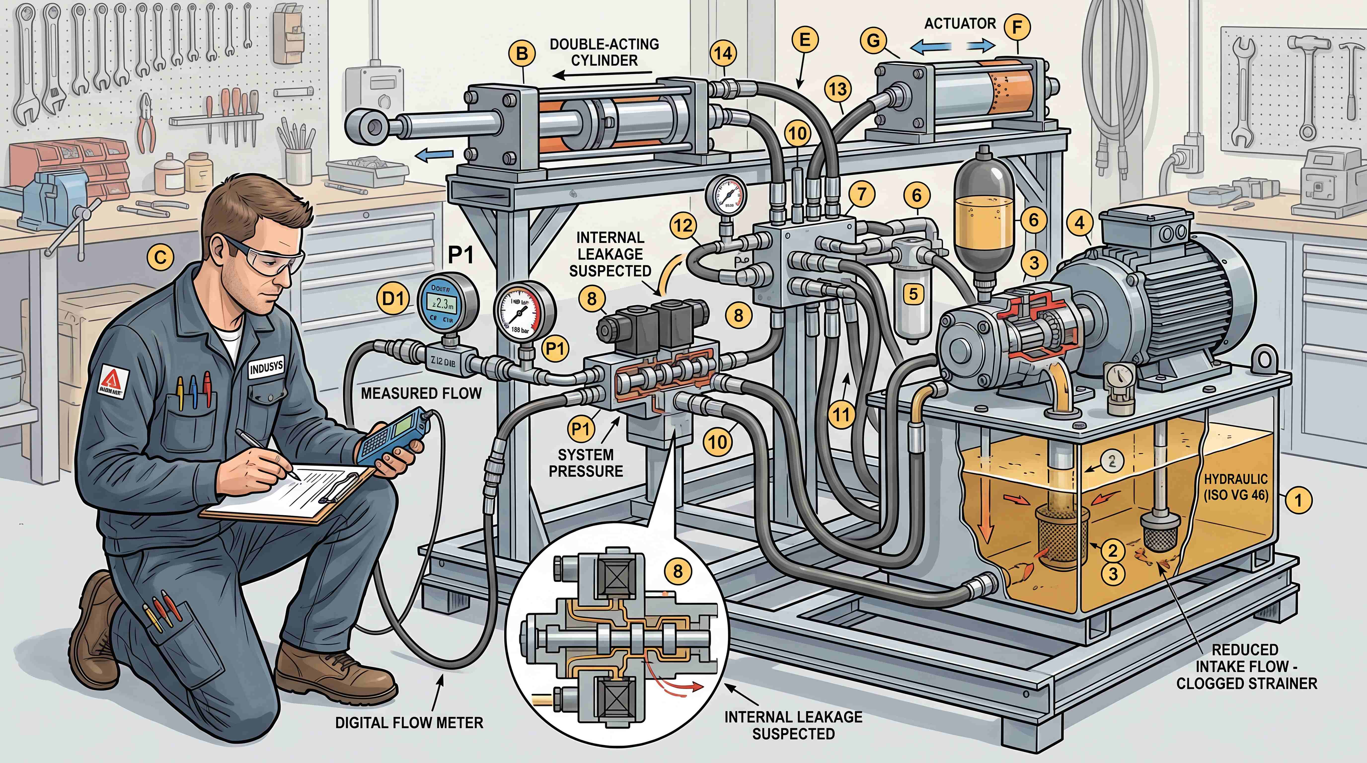
When selecting manifolds, consider test points. Pressure test ports at pump supply, actuator ports, pilot lines or branch circuits can save significant diagnostic time. Good test points turn troubleshooting from guessing into measurement.
Documentation should include the hydraulic schematic, manifold drawing, port labels, valve list, cartridge cavity map, coil voltage, seal kits, torque values and adjustment settings. This is especially important for OEM equipment.
Serviceability also affects safety. Technicians need to identify pressure lines, release stored pressure and avoid accidental actuator movement. A clear manifold layout helps.
The best hydraulic systems are not only designed for assembly. They are designed for the full machine lifecycle.
A Practical Selection Workflow for Hydraulic Valves and Manifolds
A structured workflow can help avoid selection errors.
Start by defining the machine action. Describe what each actuator must do: extend, retract, rotate, hold, lower, press, clamp or unload.
Next, define pressure and flow. Identify normal pressure, maximum pressure, shock conditions, required actuator speed and pump flow.
Then identify the circuit type. Determine whether the system is open center, closed center, load-sensing, fixed displacement, variable displacement, single function or multi-function.
After that, select valve functions. Decide where directional control, pressure relief, flow control, check control, load holding, unloading or proportional control is needed.
Next, choose actuation methods. Decide whether manual, solenoid, pilot or proportional control best matches the machine.
Then evaluate manifold strategy. Decide whether standard valves are enough or whether hydraulic manifold selection should move toward a custom integrated block.
After that, check packaging. Confirm installation space, port orientation, hose routing, coil access, adjustment access and test point locations.
Then review safety. Confirm load holding, relief protection, hose failure risk, controlled lowering and emergency behavior.
Next, review environment. Check temperature, vibration, contamination, moisture, corrosion, duty cycle and electrical protection.
Finally, review lifecycle support. Confirm documentation, replacement parts, labels, service access and troubleshooting strategy.
This workflow keeps component selection connected to the real application.
Common Selection Mistakes to Avoid

One common mistake is choosing valves by port size only. Port size does not confirm pressure, flow, spool function, leakage behavior or control method.
Another mistake is choosing by maximum pressure alone. Pressure rating is necessary, but it does not guarantee correct flow capacity or circuit function.
A third mistake is ignoring valve center condition. Directional valves with different neutral positions can completely change system behavior.
A fourth mistake is using relief valves as continuous operating controls. This wastes energy and creates heat.
A fifth mistake is using a check valve where a counterbalance valve is required. Load control requires more than reverse-flow blocking.
A sixth mistake is undersizing valves or manifold passages. This creates pressure drop, heat and slow motion.
A seventh mistake is overusing advanced valves. Proportional valves are valuable when needed, but they add cost and complexity.
An eighth mistake is designing a compact manifold without service access. A small block is not good if technicians cannot adjust or diagnose it.
A ninth mistake is ignoring contamination. Dirty oil can ruin even well-selected valves.
A tenth mistake is failing to document the system. Without drawings, labels and settings, future maintenance becomes unreliable.
Avoiding these mistakes improves reliability more than simply buying more expensive components.
Conclusion: The Best Hydraulic Component Is the One That Fits the Application
The best valve or manifold is not always the strongest, the smallest, the most advanced or the cheapest. It is the component that fits the application.
Effective hydraulic valve selection begins with machine behavior. What must the actuator do? What pressure and flow are required? What safety risks exist? What control method is needed? What environment will the component face?
Effective hydraulic manifold selection begins with system organization. Does the machine need compact integration? Are there too many hoses and fittings? Is repeatable production important? Will technicians need clear test points and labels? Is a standard manifold enough, or does the application justify a custom hydraulic manifold?
To choose hydraulic valves and manifolds correctly, think in terms of the complete hydraulic control circuit. Pressure, flow, direction, load holding, service access and lifecycle cost all interact. A component that looks correct in isolation can be wrong inside the system. A well-selected component supports the entire machine.
For buyers, engineers and maintenance teams, the main lesson is clear: start with hydraulic system requirements, not with product names. When the application is understood, the right valve and manifold choices become much easier to identify.
A hydraulic system is successful when force becomes controlled motion. Valves and manifolds make that control possible. That is why choosing them carefully is not just a purchasing task. It is a machine design decision.
#HydraulicManifoldSelection
#ChooseHydraulicValves
#ChooseHydraulicManifold
#HydraulicValveFlowRate
#HydraulicValvePressureRating
#CustomHydraulicManifold
#HydraulicControlCircuit
#HydraulicValveApplication
#HydraulicSystemRequirements
#HydraulicSystemDesign
#IndustrialHydraulics
#MobileHydraulics
#FluidPower
#IndustrialComponents