
Does Your Warehouse AMR Need a 6-Axis or 9-Axis IMU
More Axes Help Only If the Added Reference Is Useful
A warehouse AMR does not automatically gain better heading by replacing a six-axis inertial package with a nine-axis one. The additional magnetometer can provide a useful directional observation, but it measures the field at its installed location. Steel structures, electrical equipment, the robot itself, and its changing load can influence that observation. The purchasing decision is whether the robot can use it appropriately throughout the intended operation.
The choice is becoming more concrete. On October 13, 2026, TDK announced worldwide distribution availability of PositionSense, a two-chip solution combining six-axis inertial sensing, a three-axis TMR magnetometer, and fusion and calibration software. TDK describes magnetic-shock resistance and recovery features. Those are manufacturer capabilities to investigate; they do not establish immunity to persistent local-field distortion in a particular warehouse.
Six-axis development is also continuing. ST's September 22 announcement introduced new devices including the industrial ISM6HGK256X. It described the chips as available while scheduling their evaluation adapters for November 2026. The two announcements illustrate current sourcing alternatives, not a measured comparison between the products or a reason to treat six axes as an obsolete category.
For an AMR buyer, the useful question is narrower than which package contains more sensors. What keeps the robot's heading estimate useful during ordinary travel, while carrying its approved loads, and when a proposed magnetic reference disagrees with the rest of the navigation system?
A 6 axis IMU may be an appropriate purchase when the robot already obtains heading corrections from suitable localization observations. A 9 axis IMU may be appropriate when its magnetic information adds a demonstrated benefit and the system can recognize when that information should have less influence. Some nine-axis products can also operate without magnetic fusion, making hardware selection and reference selection separate decisions.
The broader mobile robot sensor selection guide covers the roles of complementary sensors. This comparison focuses on whether an added magnetic heading reference earns its place in the installed robot.
Choose the Output Before Choosing Six or Nine Axes
In this article, six axes means three accelerometer channels and three gyroscope channels. Nine axes adds three magnetometer channels. The term inertial measurement unit is sometimes reserved for the accelerometers and gyroscopes, although nine-axis IMU is common market terminology. Neither description means that the module independently measures nine spatial dimensions or provides absolute XYZ position.
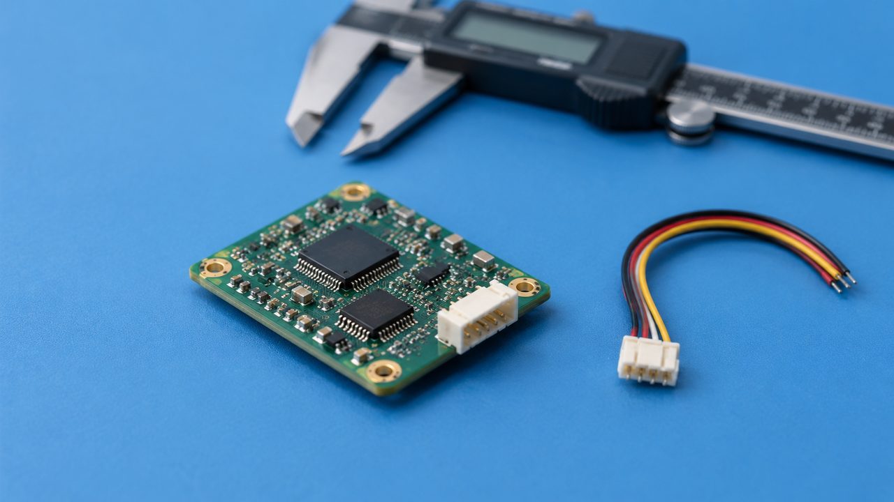
The accelerometers measure specific force, while the gyroscopes measure angular rate. An estimator can use their measurements to follow orientation changes. Gravity can help constrain tilt when the estimator accounts appropriately for vehicle acceleration and other effects. It does not supply an independent yaw reference for a typical MEMS AMR implementation.
ST's MotionFX user manual provides a specific example: its six-axis mode combines acceleration and angular-rate measurements, while its nine-axis mode also uses magnetic measurements. The latter references heading to magnetic north; the former does not supply that absolute heading reference. This is an implementation example, not a universal specification for every fusion library.
Raw measurements and an attitude solution are different purchases
A component supplying acceleration and angular rate leaves substantial estimation work to the robot computer. An AHRS (attitude and heading reference system) adds processing that estimates orientation. The buyer should establish which output the application will consume and which observations influence it.
| Offered output | What it represents | Question for the buyer |
|---|---|---|
| Acceleration and angular rate | Measurements in defined sensor axes | Which robot estimator converts them into the required motion estimate? |
| Magnetic field vector | The local field measured along three axes | How will its relevance to heading be assessed? |
| Fused orientation | An estimate produced from selected observations and assumptions | Which references are active, and how is their influence reported? |
| Position or navigation state | A broader estimate requiring additional information and processing | What aiding sources and operating conditions support the claim? |
A smooth yaw output can be convenient without being correct. Ask for access to the underlying observations and enough status information to explain the output when it changes. A robot integrator should be able to tell whether a heading adjustment came from magnetic measurements, another aiding source, or the estimator's internal prediction.
Also establish where fusion happens. If an onboard module already combines magnetic and inertial measurements, the host should not treat its output as though it were a completely independent observation of the raw measurements that produced it. Have the integration team explain the intended information flow and uncertainty treatment rather than purchasing two attractive outputs that are difficult to combine consistently.
Magnetic north is not automatically the warehouse map direction
A magnetic heading, a geographic heading, and the robot's map-frame yaw are different references. The warehouse map may use an aisle as its primary axis. Geographic north differs from magnetic north, and local disturbance can further alter the field observed by the device. Installation alignment and the required frame transformation must be established separately.
Typical MEMS six-axis fusion lacks an independent long-term yaw reference, but that is not a claim about every inertial instrument: higher-grade gyrocompassing is a separate technology and operating case. For this AMR decision, ask what the proposed system actually uses to constrain yaw and how that reference relates to the map.
The Magnetometer Sees the Robot as Well as the Warehouse
Magnetic interference is not limited to a brief burst of noisy readings. A nearby object can change the direction of the measured field while the output remains quiet. A robot can therefore produce a stable magnetic heading that is unsuitable as a reference for its intended map direction.
VectorNav's magnetic-error primer distinguishes the Earth's field from disturbances associated with the surrounding environment and the sensor installation. It describes hard-iron bias and soft-iron distortion. For procurement, the useful distinction is between an effect that remains fixed relative to the sensor and one that changes with location, equipment state, or payload.
Placement changes the magnetic problem
Look at the proposed mounting position inside the complete vehicle. A convenient space beside a drive motor or a high-current cable may be a poor place to obtain a magnetic reference. Moving the module can change its exposure, but available space, vibration, mechanical protection, and the required alignment also constrain the installation.

Do not accept a universal separation distance without a basis in the offered device and robot. A small AMR may not provide the clearance assumed by guidance written for a large vehicle. Ask the supplier to evaluate the feasible locations and identify which one supports the claimed behavior under the robot's electrical and mechanical operating conditions.
Cable routing belongs in that decision. The relationship between the sensor and nearby power paths should remain representative between evaluation and production. A later packaging change can alter the magnetic environment even when the sensor part number remains unchanged. The relevant purchasing boundary is the installed arrangement, not only the circuit board.
A changing load can change the reference
A magnetic assessment of an empty chassis may not represent a robot carrying steel tooling, metal containers, or a different load carrier. Consider which materials enter the sensor's vicinity and whether they move relative to it during lifting or handling. Their influence should be assessed rather than inferred from the nominal payload weight.
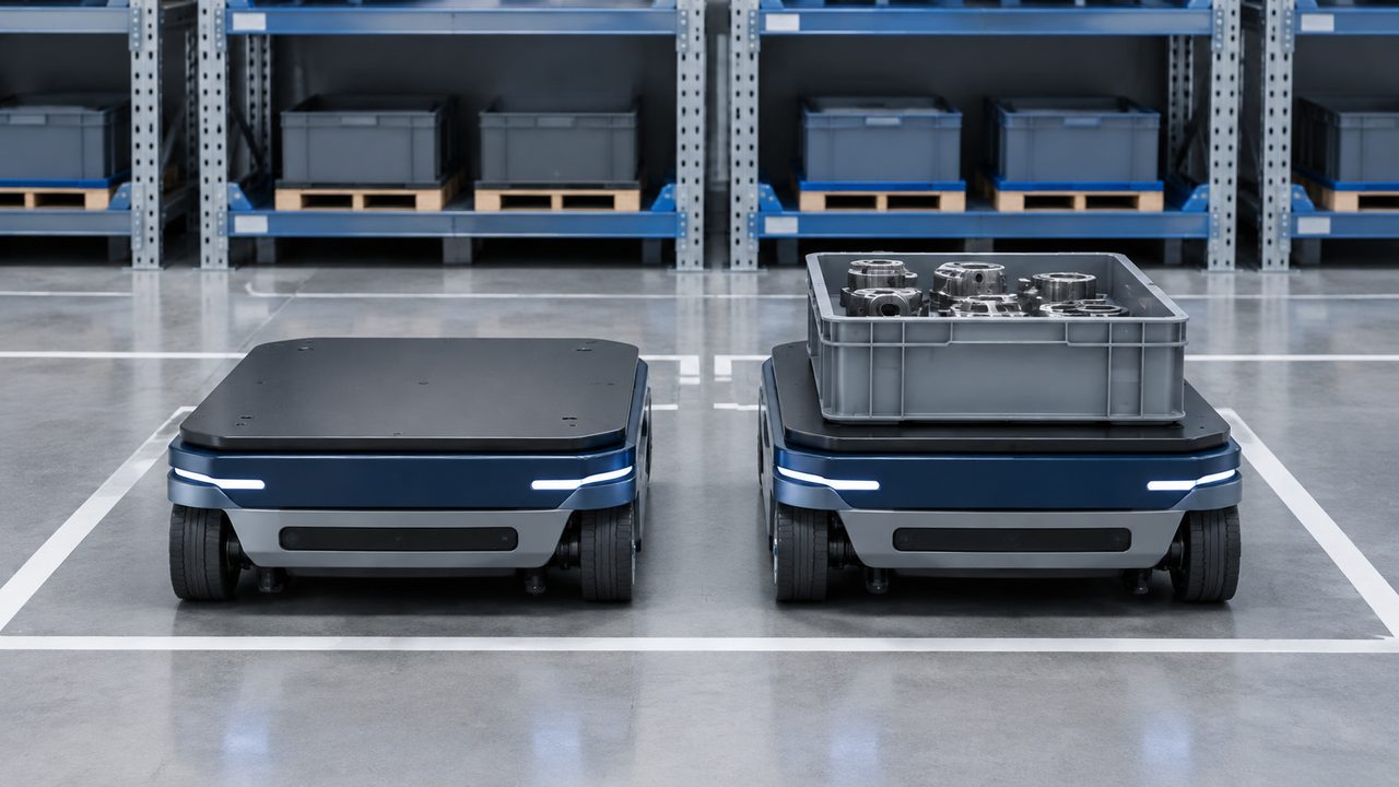
For example, imagine an AMR whose heading is consistent with an independent reference when empty but changes after a metal fixture is loaded, although the chassis has not rotated. This is a hypothetical diagnostic case, not a reported experiment. It would direct attention toward the changed magnetic environment before anyone interpreted the yaw change as actual robot motion.
The same distinction applies to surrounding structures. A reference that behaves acceptably in an open commissioning area may behave differently near a rack, door, charger, or piece of energized equipment. Conversely, the presence of steel somewhere in the building does not prove that every magnetic observation is unusable. The relevant quantity is the installed measurement's usefulness in the actual operating conditions.
Assess field direction as well as magnitude. A plausibility check on field strength can be useful, but equal magnitudes do not imply equal directions. A quiet trace or a value inside a broad expected range is therefore insufficient evidence that magnetic heading is correct.
This is also why magnetic-shock recovery should not be read as a blanket warehouse guarantee. Recovery from a specified magnetic exposure and correct interpretation of a continuously altered local field are different capabilities. Ask what the manufacturer means by the feature and what evidence supports its use in the intended installation.
Decide What Constrains Heading When Magnetic Data Is Set Aside
The central system question is what happens while magnetic information is considered unsuitable. Excluding a bad observation can prevent it from pulling the estimate in the wrong direction, but exclusion does not create a replacement heading reference. The robot still needs an adequate estimate for the work it is performing.
SBG Systems' installation guidance makes an important product-specific distinction: its estimator can handle short magnetic disturbances, while a field direction changed for a long period can eventually influence heading alignment. Buyers should therefore ask about disturbance duration and estimator behavior, not accept a general statement that magnetic disturbance is “handled.”
Six-axis sensing can be part of an externally corrected heading estimate
A robot using a six-axis package can receive useful yaw information from LiDAR or visual localization when those observations are valid. Other vehicle measurements may also contribute under their own assumptions. The absence of a magnetometer does not mean the complete robot has to operate indefinitely using an unaided gyroscope.
The question is whether those references are available where the robot needs them. A map-based estimate may be well constrained in one aisle and weak in another. A wheel-based contribution depends on the relevant traction and motion conditions. Buying an additional magnetic channel is useful only if it improves the periods or tasks that are otherwise limiting.
Pay particular attention to overlapping limitations. If magnetic data becomes unsuitable only where map-based heading is strong, rejecting it may have little operational consequence. If it becomes unsuitable in the same area where the available scene provides weak localization constraints, the robot faces a different problem. Assess that combination explicitly; a supplier's successful demonstration of each reference in isolation does not establish that the overall arrangement covers the gap.
The existing guide to sensor fusion for mobile robot navigation explains the complementary roles. Here, identify the specific heading reference used when magnetic data is accepted, reduced in influence, or rejected. The answer should describe the proposed system rather than list sensors that happen to be installed.
Put gyroscope drift in the context of time without correction
For an original illustrative calculation, assume that a heading-rate estimate contains a constant residual error of 0.03 degrees per second and receives no heading correction. Integrating that error gives 0.6 degrees after 20 seconds and 1.8 degrees after 60 seconds. These are hypothetical values chosen to explain accumulation, not specifications for either announced product.
The calculation includes only a constant residual rate error. It is not a full error model and does not predict real performance under temperature change, vibration, motion, or other estimator effects. Its purchasing value is to show why the duration without a usable correction matters. A tolerance that can be met through a brief interruption may not be met through a long one.
Ask the supplier to relate the proposed sensor and estimator to the robot's own heading-error budget. Do not treat a single drift figure as a guarantee over every route. If the robot has a suitable independent correction throughout operation, the budget may favor a strong six-axis option. If it has predictable periods without that correction, demonstrate how the chosen arrangement manages them.
Startup needs its own explanation
Initial heading and heading maintained during travel are different purchasing concerns. A robot starting from a known orientation in a mapped docking location may already have a suitable reference. A robot that can be moved while powered down needs a way to establish its current orientation before relying on a stored estimate. Determine what the proposed application actually assumes.
A magnetometer can be considered for that initial observation, but startup beside a charger or under a metal load still requires an assessment of the local field. Test the intended startup location and load condition rather than assigning the sensor a universal initialization role. Also ask how the application distinguishes an initialized estimate from one that remains uncertain.
Reaccepting magnetic data is also a design decision
Suppose the robot leaves an area where magnetic information was rejected. The newly available magnetic direction may differ from the heading maintained during that period. Ask how the estimator evaluates the returning observation, how its influence changes, and whether the application sees an abrupt correction or a gradual adjustment.
Neither response should be declared correct without considering the task. A sudden change can disrupt a motion estimate; a slow adjustment can preserve continuity while retaining an error for longer. The supplier should explain the behavior and make its consequences observable. The buyer should assess it against the robot's control and localization needs.
For outdoor portions of a route, another possible reference is discussed in the site's dual-antenna GNSS heading guide. Its availability and installation requirements differ from magnetic heading. It should not be assumed to solve the indoor warehouse case merely because the robot can sometimes obtain satellite measurements.
Calibration Has a Boundary Around the Installation
IMU calibration can describe several different activities. Factory compensation of inertial bias or scale factor, determination of the sensor's orientation relative to the chassis, and compensation of magnetic effects are related to measurement quality but are not interchangeable. Ask which activities the purchased product includes and which remain the integrator's responsibility.
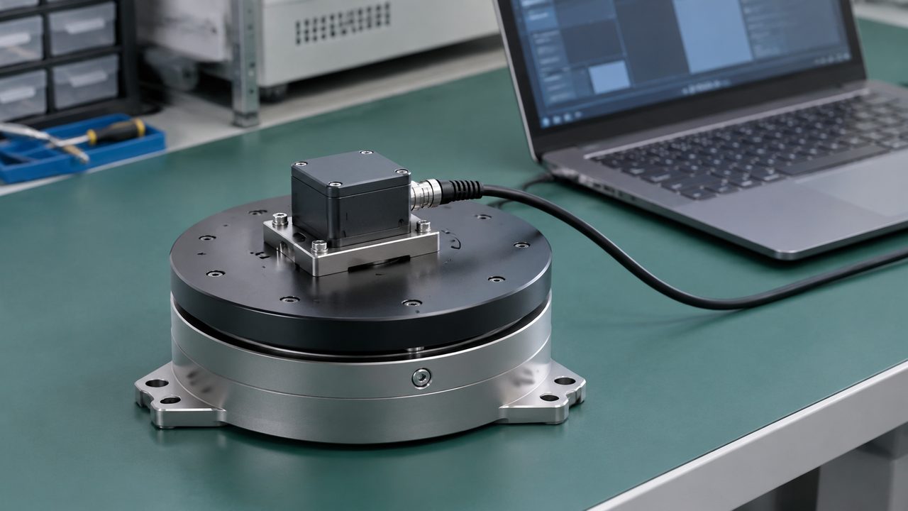
VectorNav's hard- and soft-iron calibration explanation describes compensation for internal, non-time-varying magnetic disturbances. That provides a useful boundary for magnetometer calibration: fitting a fixed installation does not, by itself, establish correct heading beside every external structure or with every changed load.
Imagine calibrating the sensor while the robot carries one metal fixture. If a different fixture changes the measured field, the earlier fit should not be assumed to cover the new condition. Repeating a calibration may produce another fit, but it does not answer whether that fit remains appropriate throughout the changing operation.
Separate a successful fit from useful heading
A calibration tool may report convergence or a favorable quality indicator. Establish what that indicator measures. It may describe how well collected observations fit a model rather than independently prove the robot's heading against the required reference. A fit and an operational validation answer different questions.
The available calibration motion also matters. A ground robot normally explores a limited range of orientations compared with a handheld sensor rotated freely in three dimensions. Ask whether the supplier's procedure and model are suitable for the installed vehicle. Do not assume that a bench demonstration involving arbitrary rotations can be reproduced safely or meaningfully on a loaded AMR.
Mechanical alignment should have its own record. A correctly compensated field vector still needs the relationship between sensor axes and vehicle axes. A board mounted at a different angle can change the interpretation of its output unless that relationship is accounted for. Magnetic correction alone does not establish the map-frame transformation.
Discuss the conditions under which calibration is retained, reassessed, or invalidated. Changes to mounting hardware, nearby equipment, or load configuration can be relevant. The point is to define a manageable operating boundary, not to require an elaborate calibration ritual after every ordinary movement.
If the required magnetic calibration cannot be maintained economically across the real load and route combinations, that is a selection result. It may favor relocating the magnetic sensor, limiting where its data influences heading, or choosing an arrangement that relies on other observations. More calibration is not automatically the best remedy.
The site's AMR sensor diagnostics, calibration, and maintenance guide covers the broader service process. For this purchase, keep the magnetic model's scope and the robot's alignment responsibilities explicit.
Evaluate Working States Against an Independent Heading Reference
A bare-board compass demonstration is useful for initial integration, but it cannot decide how the installed AMR will perform. The comparison needs the intended mounting location, representative electrical operation, relevant loads, and a reference that can reveal heading error without sharing the magnetic assumption under evaluation.
Inertial Sense's interference guidance recommends observing magnetic measurements, status, and heading while potential onboard sources are powered or actuated with physical geometry held fixed. That is a useful diagnostic principle. Its particular status displays and device limits should not be treated as universal acceptance criteria for other products.
Separate electrical state, load, and route location
Holding the robot's physical heading fixed while changing a relevant electrical state helps distinguish actual rotation from an apparent heading change. Compare suitable idle, energized, and actuated conditions using a controlled procedure appropriate to the vehicle. Do not create an unsafe operating condition merely to obtain a magnetic measurement.
Then examine the approved load arrangements. Keep track of the material, position, and handling state that matter to the installation. A comparison described only as “loaded” can hide substantial differences between nonmetallic goods, metal tooling, and a load carrier brought closer to the sensor by a lifting action.
| Illustrative assessment case | Question being isolated | Useful comparison |
|---|---|---|
| Fixed robot orientation; relevant electrical states changed | Does onboard operation change the magnetic observation? | Raw field, magnetic-use status, and heading against the fixed reference |
| Empty chassis and representative approved loads | Does the payload change the usable heading reference? | Heading error and reference acceptance for each arrangement |
| Representative route near structures and equipment | Where is magnetic information useful, questionable, or rejected? | Time-aligned behavior against a suitable route reference |
| Exit from a disturbed area | How does the estimate respond when magnetic data returns? | Correction size, continuity, and effect on the intended task |
This is an original assessment framework, not a standard test matrix or a set of measured results. Select conditions and acceptance limits from the robot's operational needs. Its purpose is to keep different causes visible so that the purchase can address the actual limitation.
Make the reference independent enough to reveal the problem
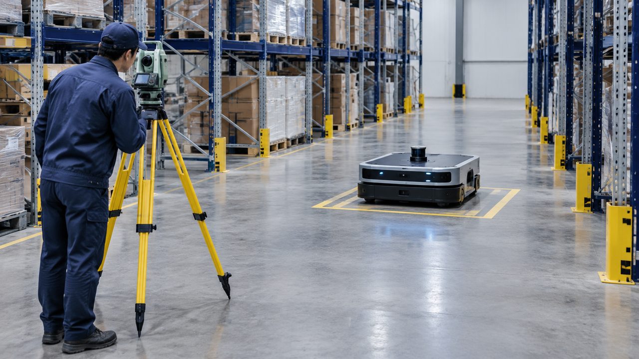
A second magnetic compass near the same robot may agree because it experiences a similar disturbance. Agreement between the two would not establish the required map heading. Use a reference appropriate to the experiment, such as controlled orientation geometry for a stationary comparison or independently assessed localization for a route comparison.
The reference itself needs understood uncertainty and timing. If route localization is weak in the area of interest, it cannot simply be labeled ground truth. Explain how its suitability was established and avoid treating a robot's own fused estimate as an independent benchmark when the candidate magnetic measurements already influence that estimate.
Where the product allows it, comparing six-axis and nine-axis fusion on the same installed hardware can help isolate the magnetic contribution. It does not eliminate every difference: initialization, estimator settings, and the remaining references still matter. Preserve those conditions so that an apparent improvement can be explained.
A comparison between two different commercial modules answers a broader question. Their gyroscopes, accelerometers, filtering, compensation, and processing may differ along with the presence of magnetic sensing. If one performs better, attribute the finding to the tested product and configuration. Do not turn that result into a general claim that adding or removing three magnetic channels caused every observed difference.
Report more than average heading error. An average can hide a large departure under one load, a long period of rejected data, or an inconvenient correction when a reference returns. Show the operating case that creates the limitation and explain its effect on the robot's actual task.
Also compare the benefit with magnetic fusion disabled. If the robot already meets its heading requirement through its other observations, an added magnetometer may provide little operational improvement. If it materially reduces uncertainty in a known gap without introducing unacceptable errors elsewhere, the value of nine-axis sensing becomes concrete.
Purchase the Heading Capability the Robot Can Maintain
The 6 axis vs 9 axis IMU decision has three reasonable outcomes. Buy a six-axis solution when its inertial performance and the robot's other references meet the requirement. Buy a nine-axis solution when magnetic information adds useful heading support over the approved operating conditions. Or buy nine-axis hardware for flexibility while selectively reducing or disabling magnetic fusion, if the product and application support that behavior.
LP-Research's selection guide explicitly describes switching its nine-axis products to six-axis fusion in software. That is a concrete example of the third option, not a guarantee that every module exposes the same control. Confirm the offered product's modes and what changes when a mode is selected.
For the chosen IMU sensor, compare the inertial characteristics needed by the task as well as the presence of a magnetometer. Axis count does not establish bias stability, noise, useful bandwidth, temperature behavior, timestamp quality, or the suitability of the mounting. A strong magnetic reference does not compensate for every other weakness, and a good gyroscope does not remove the need for a suitable long-term reference.
Price the installed benefit and its continuing effort
The component price difference may be smaller than the effort required to obtain usable magnetic heading. Include feasible mounting changes, characterization of approved payloads, calibration work, integration of reference status, and support for the selected estimator behavior. Distinguish one-time engineering from activities repeated across the fleet or during service.
A low-cost magnetometer that is rejected through most of the important route may still have a limited useful role, such as a supported startup observation in an appropriate location. Price that actual role rather than assigning it credit for continuous heading correction. Conversely, a more expensive solution can be worthwhile if it removes a demonstrated operational limitation with manageable installation requirements.
Ask the supplier to describe the delivered behavior in terms the robot team can use: which measurements are available, which references influence the estimate, what status is exposed, and what the application can expect when the magnetic environment changes. Tie the claim to the chosen mounting, operating modes, and relevant load conditions.
Keep protective-function claims separate from this comparison. Neither six nor nine sensing axes establishes a safety integrity level or qualifies an entire AMR safety function. The decision here concerns navigation information and its usefulness; any credited protective function requires its own applicable device and system evidence.
The preferred purchase is the one that gives the robot a heading estimate it can explain and sustain. Additional magnetic channels earn their value when they improve the required observation and the system can manage their limitations. When they do not, six-axis sensing with appropriate external heading information can be the more suitable design.
Focused FAQ
Is a 9 axis IMU always more accurate than a 6 axis IMU?
No. The added magnetic channels provide another possible heading observation, not a universal accuracy improvement. Their value depends on the installed field, calibration scope, estimator behavior, and the other references available to the robot. Compare complete operating results for the proposed products.
Can a six-axis IMU measure yaw?
It can support estimation of yaw changes from angular-rate measurements. Typical MEMS six-axis fusion does not independently establish a long-term absolute yaw reference. The robot can obtain heading corrections from other suitable observations, such as valid map-based localization.
Will magnetometer calibration remove warehouse interference?
It can compensate effects represented by the calibration model, such as suitable fixed installation distortions. It does not automatically validate changing external fields, new metal loads, or altered hardware. Establish the conditions covered by the procedure and assess heading against an appropriate independent reference.
Does magnetic-shock recovery mean the heading remains correct near steel?
No. Recovery from a specified magnetic exposure is different from interpreting a persistent altered local field. Ask what the manufacturer tested and how the estimator treats an unsuitable magnetic reference over the duration relevant to the robot.
Can nine-axis hardware be used without magnetic heading?
Some products support six-axis fusion or another way to reduce or disable magnetic influence. Confirm that capability for the offered module and software. Also establish which observation constrains heading while the magnetic data is not being used.
Does an AHRS provide absolute warehouse position?
An attitude and heading output is not an absolute XYZ position measurement. Position requires additional information and estimation appropriate to the application. Clarify the product's outputs and aiding assumptions rather than inferring position capability from axis count or an orientation display.
Official Sources
- TDK: PositionSense worldwide distribution announcement, October 13, 2026.
- STMicroelectronics: New six-axis motion sensors, September 22, 2026.
- STMicroelectronics: MotionFX user manual UM2220.
- VectorNav: Magnetic Error Sources.
- VectorNav: Magnetometer Hard and Soft Iron Calibration.
- SBG Systems: Inertial Sensor Installation.
- Inertial Sense: Interference Considerations.
- LP-Research: How to Choose an IMU.


