
Should Your AMR Use Solid-State or Mechanical LiDAR
The Better Buy Depends on the Robot's Sensing Layout
An AMR should use the LiDAR arrangement that provides the required observations throughout its route at an acceptable installed cost. That may be a rotating sensor, several directional solid state devices, or a combination. The scanning mechanism influences the design, but it cannot decide the purchase independently of mounting position, usable coverage, target characteristics, timing, and the computer that consumes the measurements.
Recent product developments make this a practical sourcing question. In its October 9, 2026 announcement, RoboSense said its fully solid-state E2, introduced in July, achieved its first mass-production deployment in September. That is evidence of progress for a named product. It does not establish that every AMR application should replace its rotating scanner, or that every solid-state design has the same sensing characteristics.
The buyer's challenge is to compare complete alternatives. A compact front-facing unit and a roof-mounted rotating unit are rarely equivalent purchases when considered individually. One may concentrate measurements on the travel direction; the other may observe surrounding geometry through a wider azimuth range. If the robot reverses, turns in place, or moves sideways, the first proposal may require additional units before the comparison becomes meaningful.
The useful starting point for solid state lidar vs mechanical lidar is therefore a layout drawing and a task description. Identify where the robot needs observations, at which distances, while carrying which loads. Then compare candidate designs that satisfy those needs. A lower component price is valuable only after the missing coverage, mounting work, and processing demands have been included.
This article addresses the scanning architecture decision. The broader mobile robot sensor selection guide provides the context for assigning complementary roles to cameras, inertial sensors, encoders, and LiDAR.
Identify What Actually Moves Inside the Sensor
The phrase solid state lidar does not always describe the same internal mechanism. Suppliers may use it for devices without macroscopic rotating assemblies, including products that steer a beam with a moving microscopic mirror. Other products remove mechanical beam steering altogether. Ask what moves, how illumination is distributed, and how the scene is sampled before attaching reliability or timing assumptions to the label.
ams OSRAM's technical overview separates distance measurement from scanning architecture. Time of flight and FMCW describe ranging principles; beam steering and array illumination describe scene coverage. They are different classification axes, not mutually exclusive alternatives.
Separate mechanical scanning, microscopic steering, and illumination
| Term in a quotation | What to establish | Consequence for the comparison |
|---|---|---|
| Mechanical lidar | Which optical assembly rotates or oscillates, and the resulting scan pattern | Compare the actual coverage and acquisition timing of that model |
| MEMS lidar | Whether a microscopic mirror steers the beam and how its motion is controlled | Do not interpret a small moving element as the absence of moving elements |
| Flash lidar | Which area is illuminated together and how the detector array is read | Establish spatial sampling and timing from the implementation |
| Fully solid-state scanning | How directions or scene regions are addressed without mechanical steering | Check whether acquisition is simultaneous or sequenced across regions |
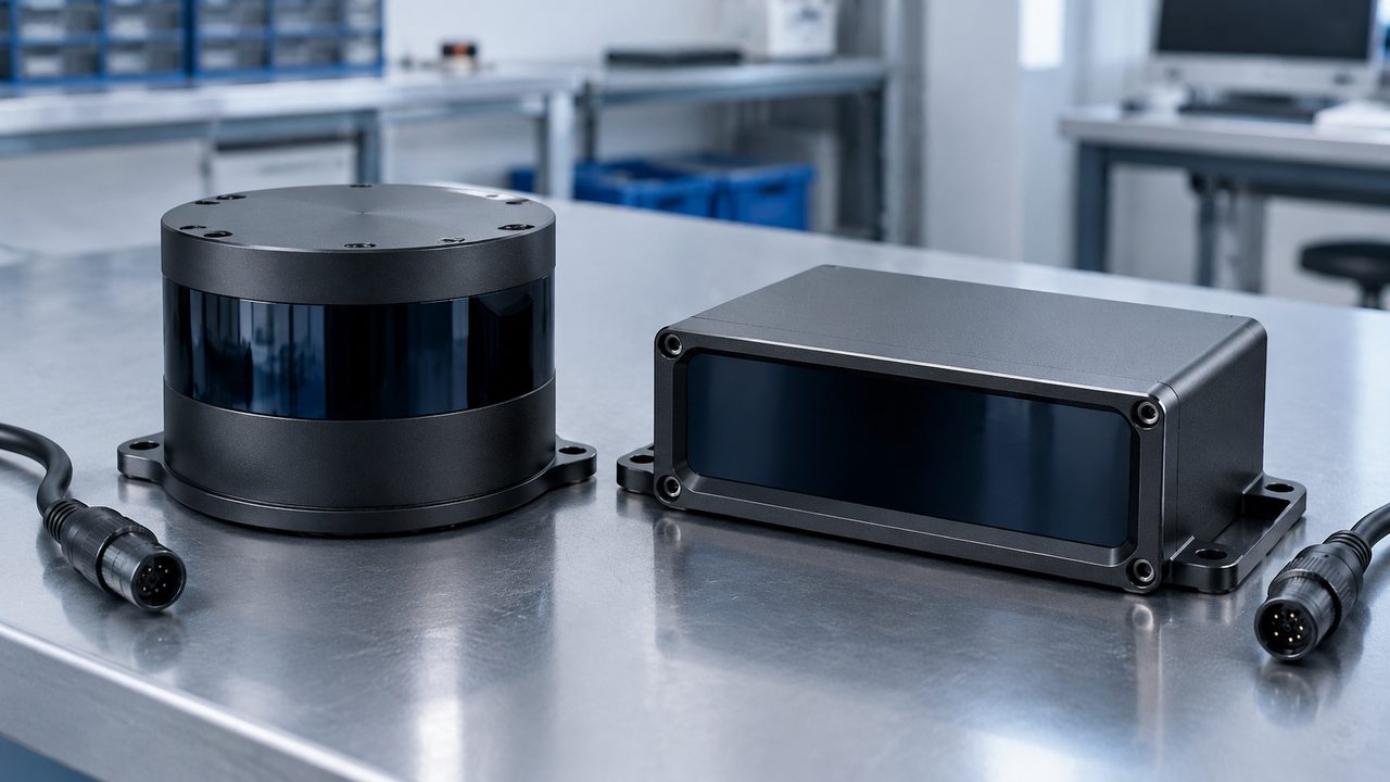
Fraunhofer IPMS's MEMS vector-scanner documentation explicitly describes mechanical scanning angles, mirror-position sensing, and closed-loop control. A MEMS device can be compact and engineered for demanding conditions while still containing physical motion. Its suitability should follow the finished sensor's specifications and qualification results, not a semantic argument about whether its movement is small enough to count.
A flash lidar generally uses broad illumination and a detector array. Some nonmechanical designs address scene regions sequentially, so confirm acquisition timing rather than assuming simultaneous measurements.
Use these definitions to improve the questions in a quotation, not to rank technologies before seeing the candidates. Ask each supplier to describe its mechanism in plain language and identify the operating mode proposed for the AMR. If an adaptive scan concentrates measurements in one area, establish what changes elsewhere. If the scan pattern repeats, establish the repetition interval relevant to the target.
A 3d lidar specification is a separate matter: it describes spatial measurement capability rather than whether the sensor rotates. Both rotating and nonrotating architectures can produce three-dimensional measurements. The site's 2D versus 3D LiDAR obstacle detection guide addresses that separate selection question.
Count Complete Coverage Before Counting Sensor Savings
A directional solid state lidar sensor can be an attractive fit when the robot needs dense observations in a defined sector. The purchasing problem changes when the proposed function requires observation around the vehicle. The number of required units must come from the installed geometry rather than from dividing a circle by the largest advertised field of view.
Consider an idealized horizontal example in which sensor origins are treated as coincident. Three 120-degree sectors can nominally add to 360 degrees, but they provide no overlap at their boundaries. Four such sectors pointed 90 degrees apart would provide 30 degrees of overlap between neighboring sectors in that simplified drawing. Actual sensors mounted at different positions on a robot will have different near-field intersections, so neither arrangement proves continuous installed coverage.
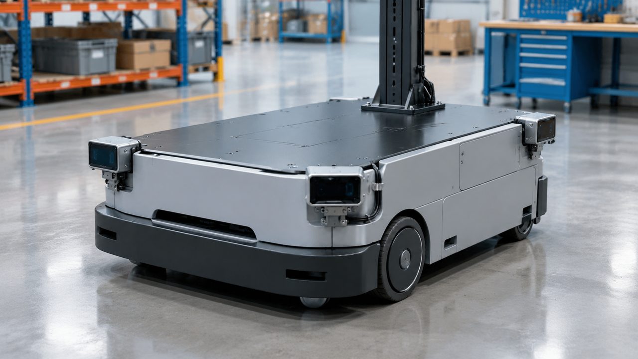
The relevant drawing includes the vehicle body, payload, lift mechanism, protective covers, and practical mounting brackets. A pallet can obscure a view that was clear during an unloaded demonstration. A low mounting position can improve the view of some nearby objects while losing a view over other structures. Moving a sensor upward changes the ground intersection of its vertical field of view and can create a different near-body gap.
Look at the route from each required direction of motion
Evaluate forward travel, reverse travel, turns, docking, and sideways motion where applicable. Define the distances at which the application needs observations in each case. Full azimuth coverage at long range does not prove useful coverage beside the robot at short range. Conversely, a directional arrangement can be sufficient if its real operating envelope is deliberately limited and the complete robot design supports that limitation.
A mechanical lidar with 360-degree horizontal coverage does not observe a full sphere. Its vertical viewing limits and installation still matter. A single roof-mounted unit may also be blocked by equipment or payload. The comparison should therefore avoid giving the rotating candidate imaginary coverage while examining every blind region of the directional candidate, or doing the reverse.
For each candidate layout, mark the regions that satisfy the required target, distance, and update conditions. Mark overlap separately from coverage: overlapping fields can assist association and transitions, but duplicate observations also consume processing and do not automatically constitute independent redundancy. Their value depends on what the application does with them.
Then count physical units, apertures to clean, brackets to protect, electrical connections, and calibration relationships. These quantities connect the geometry to cost. A compact device can be easier to package individually while a four-unit arrangement requires more installation work than one larger scanner.
The best answer may be mixed. A broad-view sensor can support surrounding scene observation while a directional device addresses a difficult local view near a pallet or docking interface. Purchase that combination because the added view solves a defined task, and include its contribution in the same cost and performance comparison as the other alternatives.
Spend Resolution Where the Target Needs It
LiDAR resolution is frequently reduced to one angular number in a comparison sheet. That number may describe an average, a selected region, one direction, or a particular operating mode. Before ranking candidates, establish where the samples occur, how the spacing changes across the view, and whether the proposed update rate uses the same settings as the advertised resolution.
The RoboSense M1 Plus product page illustrates the importance of qualifiers. It lists a 200-meter headline range, 180 meters at 10% reflectivity, and average angular resolution within a region of interest. These are model-specific statements with different conditions. The region-of-interest value should not be treated as a guaranteed worst-case spacing throughout the full view, and the headline range should not replace the target-specific range condition.
Convert angle into spacing, then test the actual object
For an illustrative geometric comparison, suppose neighboring directions are separated by 0.2 degrees and intersect a perpendicular target plane 10 meters away near the viewing axis. Their separation is approximately 10 × tan(0.2 degrees), or 35 millimeters. At 0.5 degrees it is approximately 87 millimeters. These hypothetical values show how angular spacing becomes a physical gap; they are not detection guarantees for any product.
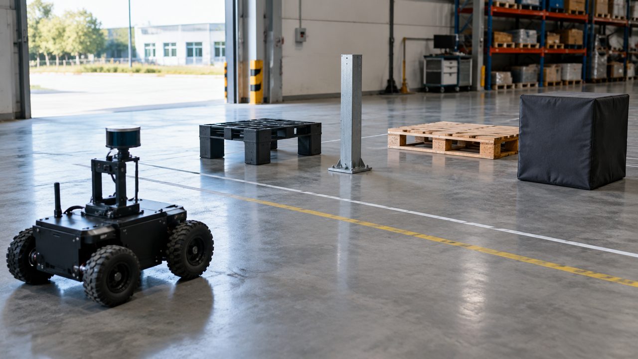
A 50-millimeter feature is not reliably detected merely because one calculated gap is smaller than its width. Its position relative to the sample pattern, orientation, beam footprint, reflectivity, and visibility all matter. The application's requirement may also need several usable points rather than one isolated return. Test the actual feature at the distances and approach angles where it must influence the robot's behavior.
Distinguish angular sampling from distance accuracy and repeatability. Dense points can describe the wrong surface or contain biased distances; accurate individual ranges can still leave a small feature between samples. Neither property should be used as a substitute for the other in a purchasing score.
Target reflectivity deserves equal attention. Ask which target properties were used for the quoted range and whether those conditions resemble the application. A dark appearance to a human observer does not provide a measured reflectivity at the sensor's wavelength. Shiny wrapping, angled metal, and mixed materials should be assessed as installed objects rather than assigned a convenient reflectivity percentage without measurement.
Build the comparison around a small set of consequential targets: a pallet opening needed for approach, a low obstacle that affects route availability, a rack edge used for localization, or a load protrusion that must remain observable. Include the actual illumination and surface conditions expected on the route. The result should identify usable observations per target over time, not merely the largest total point count.
When comparing lidar sensors, examine missing observations as carefully as successful ones. An empty region in the displayed cloud can have several explanations: the region was not sampled, the target was not visible, no usable return was obtained, or software removed the measurement. It is not automatically evidence of free space. Ask how the application distinguishes these cases and how that distinction changes its interpretation of the route.
Preserve the spatial distribution in the evaluation. Thousands of additional points on a nearby wall do not compensate for missing observations of the feature that governs the task. Compare useful coverage of that feature before giving credit for a larger aggregate point count.
Finally, distinguish extra returns from extra directions. Reporting two returns along one sampled direction can provide useful information about multiple surfaces or partial obscuration, but it does not double the number of independent viewing angles. Request enough detail to understand what the supplier's points-per-second figure counts.
Treat a Scan as Measurements Collected Over Time
The robot and surrounding objects can move while a point cloud is being acquired. A frame rate therefore does not fully describe temporal performance. The purchasing comparison needs to consider when the relevant target is sampled, how those times are represented, and how long the data takes to become usable by the application.
Ouster's motion compensation documentation explains why a rotating scan can require deskewing: measurements around a revolution are collected at different instants while the sensor translates or turns. Compensation estimates the sensor pose at those measurement times. Its effectiveness depends on the motion estimate and its timing, rather than on frame rate alone.
In a hypothetical example, a 10 Hz scan spans 100 milliseconds. A robot traveling at a constant 1.2 meters per second moves 120 millimeters during that interval. This is the robot's displacement during acquisition, not a guaranteed 120-millimeter point-cloud error. The actual effect depends on geometry, scan direction, rotation, target motion, and compensation.
Compare target revisit time and usable information age
Ask how often the specific region that matters is observed. A fast update in a favored region may coexist with a slower update elsewhere. A frame assembled from sequential regions may contain measurements of different ages. A high output rate may also include accumulated or processed data rather than a complete set of newly acquired directions.
A fully solid-state candidate still needs an acquisition schedule: nonmechanical operation can include sequential illumination or readout. Establish which measurements the application may treat as contemporaneous.
Evaluate turning as well as straight travel. A sensor placed away from the robot's rotation center moves differently during a turn than a centrally mounted one. The mounting transform and motion estimate must represent the installed position. Test target continuity when the robot changes direction, not only when it rolls steadily toward a large wall.
At the application boundary, measure information age as well as throughput. Separate acquisition time, transport, processing, and queueing sufficiently to explain delays. A candidate that delivers fewer but timely and useful measurements may serve the task better than one whose denser data causes processing backlog. The comparison should preserve the operating conditions under which that conclusion was measured.
Include the Data Path and Computer in the Choice
The architecture label does not determine the host workload. Sensor count, output mode, return selection, fields per point, update rate, and application processing all contribute. A compact lidar sensor can create a substantial integration burden if several units feed a computer already responsible for navigation, cameras, and fleet communications.
RoboSense's September 28 Holoscan Sensor Bridge announcement concerns E2 and EM4 integration with sensor-over-Ethernet workflows. It describes direct GPU-memory delivery on supported accelerated configurations and says prototype units were delivered to NVIDIA for further integration and validation. Those statements support evaluating a specific data path; they do not establish universal availability or transfer E2's fully solid-state designation to EM4.
For each proposed layout, identify the actual network interfaces, switches, power arrangements, host connections, and software processing steps. Determine whether raw measurements are converted, copied, filtered, merged, or accumulated before the navigation application uses them. Each step has a purpose and a resource cost that should appear in the system comparison.
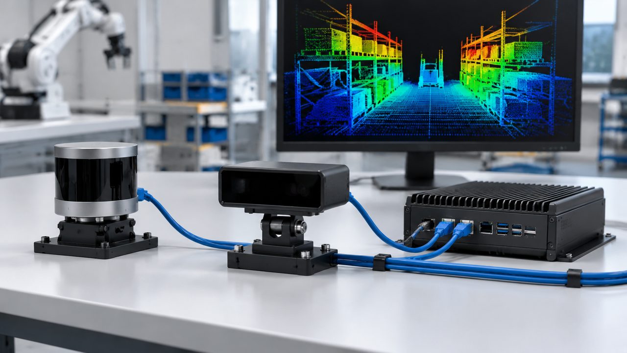
Ouster's firmware 4.0 data-format documentation provides a concrete example of why point counts alone are insufficient: output profiles use different fields and single or dual returns, with packet and column overhead contributing to the data rate. Use the documentation for the actual model and mode instead of assuming that two equal points-per-second figures produce equal network traffic.
Run the candidate arrangement on the intended class of onboard computer with the rest of the expected workload active. Record sensor input rate, application processing rate, dropped or rejected data, and information age. Monitor sustained power and temperature sufficiently to establish whether performance changes after the initial demonstration period.
Define the operating profile that gives the desired result. If the host requires reduced return information, lower update rates, or a restricted view to keep up, evaluate the resulting perception capability. A configuration adjustment is acceptable when it still meets the task; it should not be hidden behind the sensor's maximum catalog specifications.
Also establish what the application retains when multiple sensors observe the same region. Merging overlapping clouds can require alignment, filtering, and association work. Counting all incoming points as additional useful information can exaggerate the benefit while understating the processing cost.
Judge Reliability at the Model and Installation Level
Removing a rotating assembly removes that assembly's particular wear mechanisms. It does not demonstrate the service life of the complete replacement sensor. Electronics, optical surfaces, seals, thermal design, connectors, mounting stresses, and the actual duty cycle still influence operation. Conversely, a rotating sensor should not be assumed unsuitable simply because it has a moving component.
An instructive example appears in Ouster's historical L2X and Rev 06 introduction. It separately describes continuous-operation testing up to 30,000 hours and an average lifespan exceeding 100,000 hours calculated using specified MTTF methods. A calculated reliability figure is not evidence that each unit ran for that duration, and neither statement is automatically a warranty. These claims belong to the product generation discussed, not every later model.
Compare relevant stress conditions rather than slogans
Ask which qualification results apply to the offered sensor assembly and which apply only to an internal component. Compare temperature, vibration, shock, ingress protection, and operating conditions with the robot's installation. An enclosure rating answers a particular ingress question; it does not establish that an optical window stays clean enough for the application.
Consider how each layout is maintained. One elevated aperture may be easy to inspect but difficult to reach. Several low-mounted apertures may be accessible yet exposed to more contamination. Covers and cleaning arrangements can change the view or introduce optical effects, so include the intended protection in the comparison.
Ask for service experience relevant to the proposed duty, while keeping its limits visible. Fleet operating hours, return rates, and identified causes are more interpretable when the population, environment, and observation period are stated. A small favorable deployment should not be treated as proof of lifetime reliability across different applications.
Keep reliability and protective function claims separate. The SICK TIM100-3010200 data sheet lists laser Class 1 and reliability parameters while explicitly stating that this particular sensor is not a safety component. Eye safety, reliability statistics, and navigation performance therefore answer different questions. The conclusion is product-specific, not a claim that every navigation scanner is unsuitable for safety-related use.
If the proposed sensor supports a personnel-protection function, assess the applicable device and system requirements separately from this architecture comparison. The guide to safety-rated sensing versus navigation perception explains that boundary. Neither a solid-state label nor a dense point cloud alone establishes the required protective capability.
Calculate Installed Cost for Equivalent Coverage
The lidar sensor price is a useful purchasing input, but comparing one directional device with one panoramic device can create a false saving. First settle the number and placement of units that satisfy the task. Then include mounting, power, networking, compute changes, assembly, calibration, and the engineering shared across the deployment.
The following hypothetical model illustrates the accounting for 20 identical AMRs. Assume that both candidate layouts have already met the same operational requirements: one rotating unit per robot in Layout A and four directional units per robot in Layout B. The numbers are invented for this example. They are not market prices, supplier quotations, or evidence that one architecture is generally cheaper.
| Illustrative cost item | Layout A: one rotating unit | Layout B: four directional units |
|---|---|---|
| Sensors per robot | 1 × $1,200 = $1,200 | 4 × $450 = $1,800 |
| Mounts and protection per robot | $150 | $200 |
| Power and network additions per robot | $200 | $400 |
| Assembly and calibration labor per robot | $200 | $300 |
| Recurring installed subtotal per robot | $1,750 | $2,700 |
| One-time project engineering | $6,000 | $10,000 |
| Engineering allocated over 20 robots | $300 per robot | $500 per robot |
| Illustrative deployed cost | $2,050 per robot; $41,000 total | $3,200 per robot; $64,000 total |
The lower individual sensor price in Layout B does not produce a lower installed total in this example. Changing the required unit count or real quotations could change that result. The model's purpose is to keep coverage and integration in the calculation, not to assign a permanent cost ranking to mechanical lidar and directional alternatives.
Separate one-time engineering from costs repeated on every robot. A larger deployment spreads development expense across more units but does not remove recurring sensors, connectors, mounts, or installation labor. A design that looks economical in a prototype can therefore scale differently from one designed for repeatable production assembly.
Calculate operating costs separately using defensible assumptions. Consider cleaning time, inspection access, replacement labor, spare inventory, energy use, and the effect of service interruptions. Do not assign a lifetime maintenance saving to the solid-state option solely because its mechanism has fewer moving parts. If reliable field data is unavailable, show a range rather than invent a precise failure rate.
Keep the spare strategy consistent with the installed design. Four identical directional units and four different directional models create different inventory requirements. A shared spare may reduce stock complexity, but only if the replacement can serve the required positions and configurations. A common housing or connector is insufficient to establish that equivalence. Obtain the actual replacement scope before assigning a saving to standardized parts.
Finally, include the value of the capability purchased. A more expensive arrangement may enable a route, payload, or installation height that the cheaper one cannot support. If the alternatives do not provide equivalent outcomes, document that difference instead of forcing them into a price-only ranking.
Compare Both Designs on the Same Work
A useful evaluation compares complete sensor layouts on representative robot tasks. A bright point-cloud demonstration can reveal problems, but it is not the commercial outcome. The buyer needs to know whether the robot obtains useful observations soon enough, across the required route, without consuming unacceptable installation or operating resources.
Use the same representative targets, load configurations, travel directions, and environmental conditions for both candidates. Allow each design to use a justified mounting arrangement rather than forcing one into the other's bracket. Record those differences because mounting space, protection, and assembly effort are part of what the buyer is choosing.
| Task comparison | Measure at the application | Decision it informs |
|---|---|---|
| Loaded travel and turning | Visibility of required targets through the full maneuver | Whether the proposed layout provides usable coverage |
| Approach to a small or difficult feature | Usable returns and stable interpretation at the required distance | Whether sampling and target response fit the task |
| Direction changes and crossing motion | Observation continuity and information age | Whether acquisition and processing timing are suitable |
| Sustained operation with normal compute workload | Processing throughput, delays, power, and thermal behavior | Whether the proposed host and interfaces are sufficient |
Distinguish an observation limitation from an application limitation. If the sensor sees a target but the software discards it, a higher-resolution replacement may not solve the problem. If the target lies outside the installed view, tuning a detector cannot recover absent measurements. This separation helps the buyer spend money on the part of the system that changes the outcome.
Separate essential conditions from preferences before combining results into a purchasing score. An attractive average should not conceal a required loaded maneuver that one layout cannot support. Establish which requirements are mandatory, then compare cost, installation simplicity, and additional capability among the layouts that satisfy them. Where a restriction is acceptable, include it in the operational proposal rather than leaving it as an informal understanding.
Report outcomes by meaningful operating case. Keeping loaded and unloaded runs, forward and reverse travel, and relevant lighting conditions visible makes the tradeoffs easier to assess. A single overall success percentage can hide where additional sensors or a different mounting position are needed.
Then state the purchase boundary in operational terms. A directional arrangement may be preferred because it fits a constrained enclosure and covers every required approach. A rotating arrangement may be preferred because it supplies surrounding geometry with fewer installed units. A mixed arrangement may be preferred because one local task needs a view the broad sensor cannot provide.
Choose between those outcomes using the measured task performance, installed cost, and credible model-specific service expectations. The most useful supplier answer is a workable sensor layout with its operating limits clearly explained. The words solid state lidar or mechanical lidar are the beginning of that discussion, not the purchasing decision.
Focused FAQ
Is solid state lidar always better for an AMR?
No. A directional device may fit the required view and packaging well, while a rotating sensor may provide surrounding observations with fewer units. Compare complete installed layouts that satisfy the same task, including target visibility, timing, host workload, service access, and cost.
Does MEMS lidar have moving parts?
A MEMS scanning mirror physically moves to steer the beam. Some suppliers include such devices within a solid-state product category. Ask for the actual mechanism and the finished sensor's qualification results rather than interpreting the category name as a guarantee of no mechanical motion.
Does flash lidar capture every measurement at the same instant?
Not necessarily. Confirm the device's illumination and acquisition sequence. Removing mechanical scanning does not by itself establish simultaneous sampling throughout the scene.
How many directional sensors replace one 360-degree scanner?
There is no universal number. Required overlap, vertical coverage, near-field geometry, robot structure, payload, and target conditions all affect the layout. Adding advertised horizontal angles does not prove continuous coverage around an installed robot.
Why is lidar sensor price insufficient for comparing options?
The required unit count can differ, as can mounting, protection, networking, compute, calibration, and service work. Compare the cost of complete layouts that meet the operational requirements. Keep hypothetical assumptions separate from supplier quotations and measured maintenance experience.
Can a navigation LiDAR replace a personnel-protection scanner?
Only a device and system suitable for the required protective function can be used for that purpose. Eye-safety classification, point density, scanning mechanism, and reliability figures alone do not establish that suitability. Evaluate the specific safety function and its applicable requirements separately.
Official Sources
- RoboSense: Q3 2026 LiDAR sales and E2 deployment update, October 9, 2026.
- RoboSense: Integration with NVIDIA Holoscan Sensor Bridge, September 28, 2026.
- ams OSRAM: LiDAR, optical distance, and time-of-flight sensors.
- Fraunhofer IPMS: MEMS vector-scanner mirrors for LiDAR.
- RoboSense: M1 Plus product specifications.
- Ouster SDK: Motion compensation.
- Ouster: LiDAR data formats, firmware 4.0.
- Ouster: Introducing the L2X chip and Rev 06 sensors.
- SICK: TIM100-3010200 data sheet.


