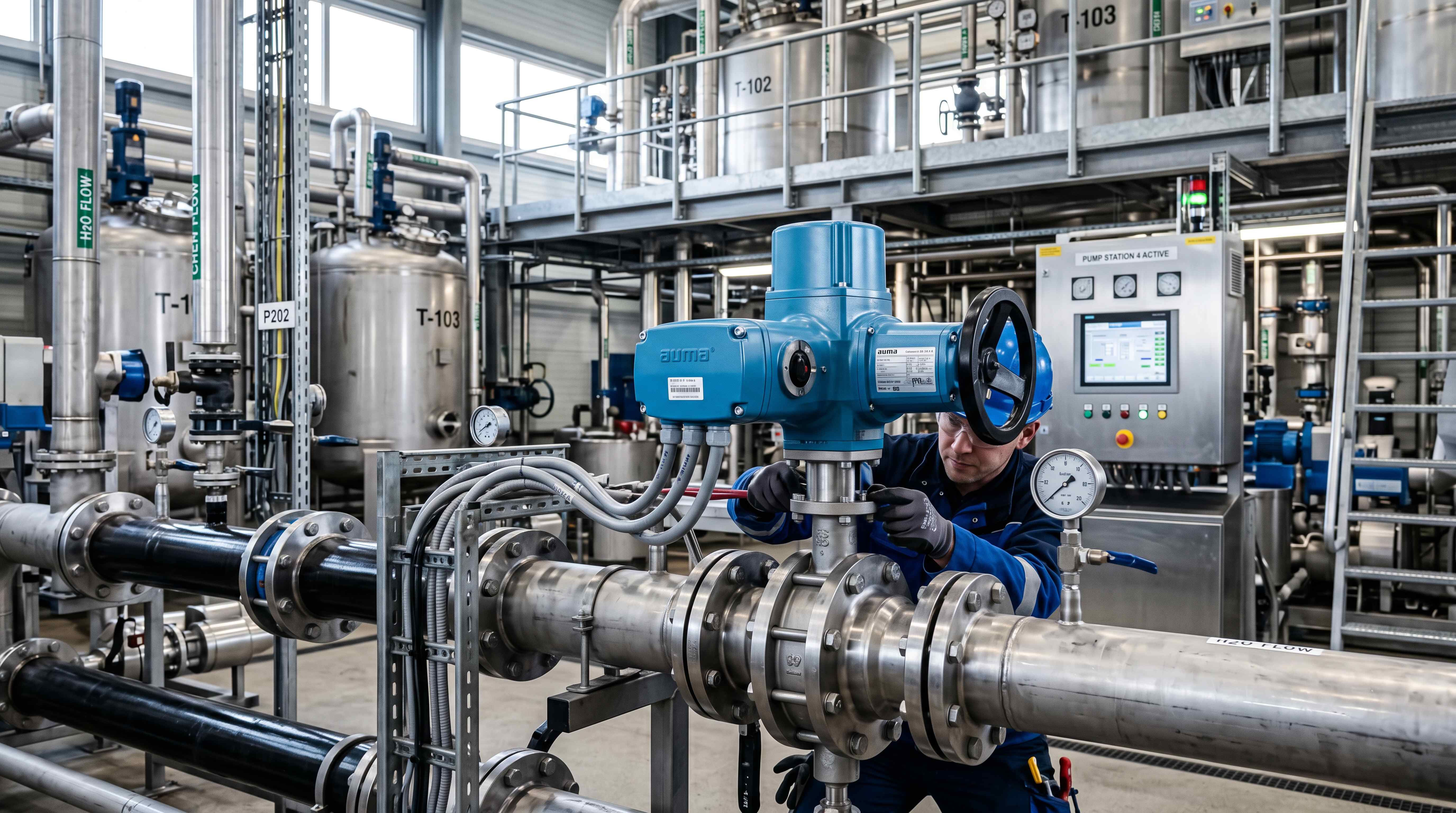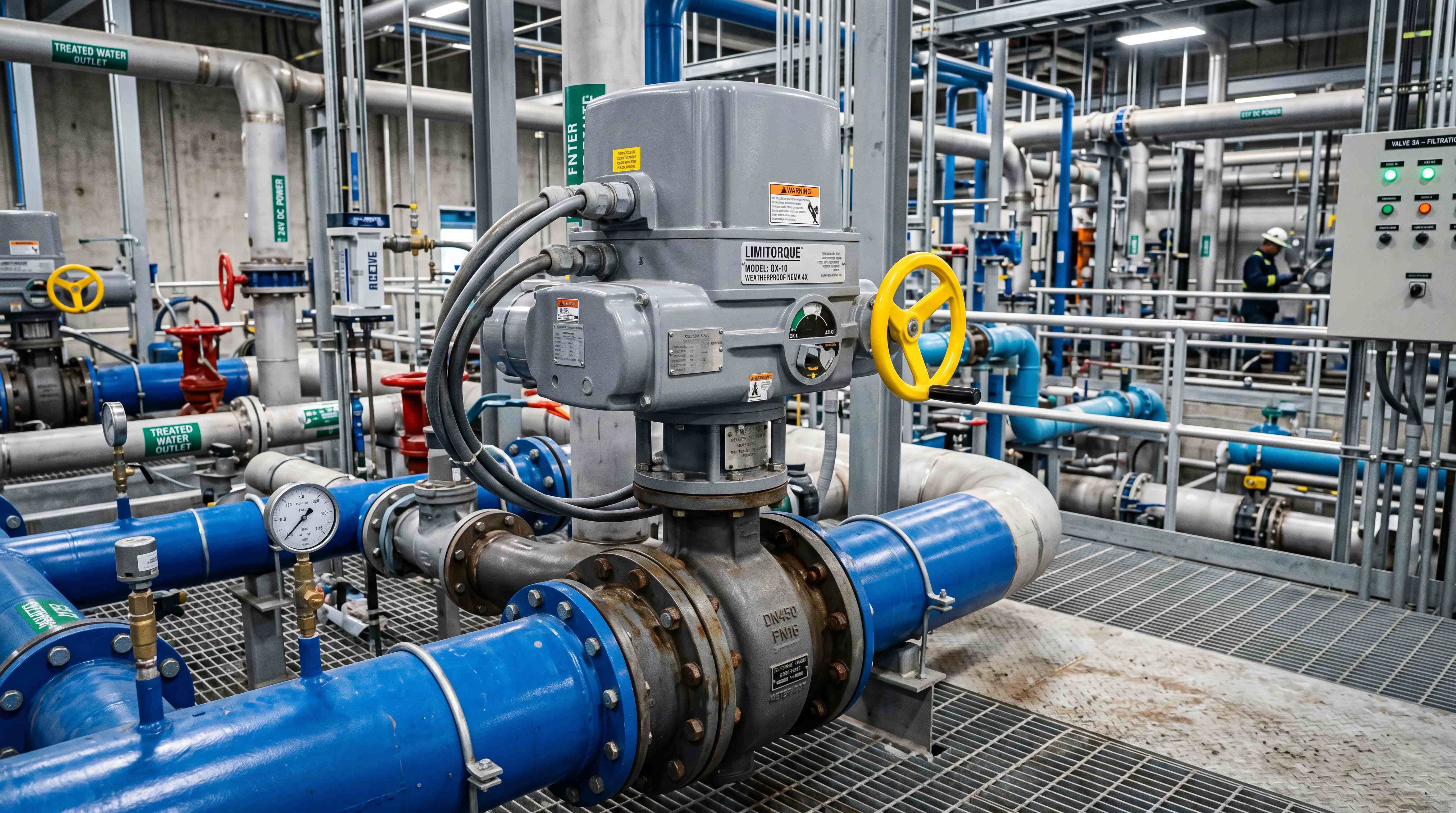
How to Select the Right Electric Actuator for Industrial Valves
Electric Actuator Selection Is a System Decision
Choosing an electric actuator for an industrial valve may look simple at first. A buyer knows the valve size, checks a torque value, finds an actuator with a matching torque rating, confirms the voltage, and asks for a quotation. In small and simple applications, this approach may sometimes work. In real industrial valve automation, however, it is often not enough.
An electric actuator is not just an accessory mounted on top of a valve. It is the device that connects the mechanical valve to the electrical control system. It must move the valve under actual process conditions, stop at the correct position, protect the valve from overload, respond to the right control signal, provide the required feedback, survive the installation environment, and remain serviceable over time.
That is why electric actuator selection should be treated as a system decision. The actuator must fit the valve, the process, the control architecture, the operating environment and the maintenance strategy. If any one of these areas is ignored, the actuator may still look correct on paper but fail in the field.
A properly selected industrial valve actuator can make a valve reliable, visible and controllable. A poorly selected actuator can create commissioning delays, incomplete valve travel, overheating, wrong feedback, control instability, leakage or premature failure. The difference often comes from whether the selection process looks beyond the basic product model.
The most important rule is this: do not select the actuator first. Define the valve duty first.
The valve type, movement, torque, operating frequency, control mode and environment should lead the decision. Only after those points are clear should engineers compare actuator models, brands and prices.
Start With the Valve Type and Valve Function

The first step in electric actuator selection is to understand what kind of valve is being automated and what that valve is expected to do.
A ball valve, butterfly valve, gate valve, globe valve, plug valve and damper do not move in the same way. They do not create the same torque demand. They are not used for the same control purpose. Selecting an actuator without understanding the valve type is one of the fastest ways to make a wrong decision.
An electric actuator for ball valve applications is usually a quarter-turn actuator. A ball valve normally rotates 90 degrees between open and closed positions. It may be used for isolation, diverting or sometimes limited flow control. Its breakaway torque can be high because the ball and seat must overcome friction at the beginning of movement.
An electric actuator for butterfly valve applications is also usually a quarter-turn actuator. A butterfly valve rotates a disc inside the flow path. It is commonly used in water treatment, HVAC, cooling systems, large-diameter pipelines and general industrial utilities. For butterfly valves, torque may be influenced by seat friction, disc position, differential pressure and flow forces.
A gate valve usually requires a multi-turn actuator because the stem must rotate multiple times to raise or lower the gate. A globe valve may require multi-turn or linear actuation, especially when used for flow control. A plug valve may require a quarter-turn actuator, but torque can be high depending on design and service condition.
Valve function is just as important as valve type. Is the valve used only for open and close isolation? Is it used for frequent operation? Is it part of a process control loop? Does it regulate flow, pressure, temperature or level? Does it serve as an emergency isolation valve? Does it need to close slowly to prevent water hammer?
The actuator should be selected according to what the valve must actually do, not only according to the valve name.
Define the Movement Type Before Checking Torque
Before discussing torque, the actuator movement must match the valve movement.
For ball valves, butterfly valves and plug valves, the common movement is quarter-turn rotation. These valves normally need about 90 degrees of rotation, so a quarter-turn electric actuator is the natural choice.
For gate valves and many globe valves, the common movement is multi-turn. These valves need several rotations of the stem to complete travel. A quarter-turn actuator cannot directly operate them unless special gear mechanisms are used.
For some control valves, dampers or process devices, linear movement may be needed. In that case, the actuator selection should consider stroke, thrust, speed and positioning accuracy rather than only rotary torque.
This movement matching step is basic but essential. If the actuator movement is wrong, no amount of control signal, enclosure protection or smart feedback can solve the problem. The actuator must first be mechanically compatible with the valve.
In professional valve actuator selection, movement type is usually the first filter. After that, engineers can evaluate torque, speed, duty cycle, voltage, control signal and feedback.
Understand Valve Actuator Torque Correctly

Valve actuator torque is one of the most important selection factors, but it is also one of the most misunderstood.
Many buyers assume that actuator torque is selected by valve size. For example, they may say, “We need an actuator for a 4-inch ball valve.” That information is not enough. A 4-inch ball valve in low-pressure clean water service may need much less torque than a 4-inch ball valve handling sticky fluid, steam, chemical media or high differential pressure.
Torque depends on valve design, pressure, seat material, media characteristics, temperature, operating frequency, stem condition and service history. It also changes during the valve stroke. The torque needed to start movement may be different from the torque needed to continue movement or seat the valve at the end.
Breakaway torque is especially important. This is the torque required to start moving the valve from a stationary position. In many ball valves, breakaway torque is higher than running torque. If the actuator cannot overcome breakaway torque, the valve will not move even if the actuator seems powerful enough during normal travel.
Seating torque is another important value. This is the torque required to properly close and seal the valve. If seating torque is too low, the valve may not seal. If excessive torque is applied, the valve seat or stem may be damaged.
For electric actuator sizing, the best practice is to obtain torque data from the valve manufacturer under the expected operating conditions. Then apply a safety factor. The safety factor should consider aging, pressure changes, media buildup, corrosion, temperature variation and uncertainty in field conditions.
A common mistake is selecting an actuator whose rated torque barely matches the valve torque. This leaves no margin for real-world conditions. Another mistake is oversizing the actuator too aggressively. An oversized actuator may damage the valve if torque protection is not properly configured.
The goal is not simply to choose the strongest actuator. The goal is to choose an actuator with sufficient torque, proper protection and good compatibility with the valve.
Match the Actuator to the Control Mode

Control mode is another major part of electric actuator selection. The actuator must match how the control system expects to operate the valve.
If the valve only needs to open and close, an on/off electric actuator may be suitable. This is common for isolation valves, tank filling valves, pump isolation valves, drain valves, simple utility valves and many automated shutoff applications.
If the valve needs to stop at intermediate positions through open, close and stop commands, a 3-point or floating control actuator may be appropriate. This type of control is often found in HVAC, building automation, mixing systems and some utility applications.
If the valve must regulate a process variable, a modulating electric actuator is usually required. A modulating actuator receives a proportional control signal such as 4-20mA or 0-10V and moves the valve to the corresponding position. This is used when flow, pressure, temperature or level must be continuously adjusted.
The control mode affects the actuator’s internal electronics, duty cycle, feedback requirement, wiring and cost. A basic on/off actuator cannot automatically become a good modulating actuator just because it can stop between open and closed during testing. Continuous positioning requires the correct control board, feedback device and duty rating.
Before selecting an actuator, define the control signal clearly:
Does the system use dry contact commands?
Does it use AC open and close signals?
Does it use DC reverse polarity?
Does it use 4-20mA input?
Does it use 0-10V input?
Does it require Modbus, Profibus, EtherNet/IP or another digital protocol?
Does the control system need open/closed feedback or continuous position feedback?
These questions should be answered before purchase. Otherwise, the actuator may arrive with the wrong control interface.
Consider Electric Valve Actuator Feedback Early
Electric valve actuator feedback should not be treated as an optional detail at the end of the selection process. It should be considered early because feedback changes how the entire valve automation system operates.
A basic actuator may provide open and closed feedback through auxiliary limit switches. This tells the PLC or control panel whether the valve has reached the fully open or fully closed position. For many on/off applications, this may be enough.
A more advanced actuator may provide analog position feedback, such as 4-20mA or 0-10V output. This tells the control system the actual valve position across the full travel range. This is important for modulating control, process monitoring and remote diagnostics.
Smart actuators may provide digital feedback, including actual position, fault alarms, torque warnings, local/remote status, motor temperature, travel history or communication status. This data can help maintenance teams detect problems earlier.
Feedback is especially important when the valve is installed in a remote, hidden, hazardous or hard-to-access location. Without feedback, the operator may only know that a command was sent. With feedback, the system can confirm whether the valve actually responded.
In a serious valve automation system, command and confirmation should be separated. The control system should not assume that a valve opened simply because it sent an open command. Mechanical blockage, wiring failure, actuator fault, power loss or manual override status may prevent the valve from moving.
For critical applications, feedback is not just a convenience. It is part of operational safety and process reliability.
Evaluate Actuator Duty Cycle
Actuator duty cycle describes how frequently an actuator can operate without overheating or exceeding its design limits. It is a crucial selection factor, especially for modulating or frequently operated valves.
Some actuators are designed for occasional open and close operation. They may open once, close once, and then rest for a long time. These actuators may be suitable for isolation service but not for continuous adjustment.
A valve that modulates every few seconds places much higher demand on the actuator. The motor, gearbox, control board and thermal design must support repeated movement. If the actuator duty cycle is too low, the motor may overheat, internal components may wear faster, and the actuator may fail prematurely.
This is a common mistake in electric actuator sizing. Buyers focus on torque but ignore operating frequency. An actuator with enough torque can still fail if it is used in a duty cycle beyond its rating.
For on/off applications, ask how many cycles per hour, per day or per month the valve will perform. For modulating applications, ask how often the actuator will adjust and how much travel each adjustment requires. For control loops, consider whether the process may cause the actuator to hunt or continuously correct position.
A stable process with occasional adjustment is very different from a fast control loop that constantly changes valve position.
Selecting the correct actuator duty cycle protects the motor, reduces maintenance and improves long-term reliability.
Check Cycle Time and Process Impact
Cycle time is the time required for the actuator to move the valve from one position to another. It is often overlooked, but it can strongly affect process performance.
A fast actuator may be useful when quick isolation is required. However, fast closure can also create pressure shock, water hammer or mechanical stress in pipelines. In water systems, closing a valve too quickly may damage pipes, pumps or fittings.
A slow actuator may protect the system from shock, but it may be unsuitable for applications that require fast response. For example, some safety-related systems need rapid valve movement. Some process control loops need responsive adjustment.
Cycle time must therefore match the application.
For a ball valve or butterfly valve, cycle time often refers to the time needed for 90-degree travel. For a multi-turn valve, cycle time depends on the number of turns and actuator speed. For a modulating actuator, response time and positioning behavior also matter.
In some systems, adjustable speed may be valuable. In others, fixed speed is acceptable. The key is to think about what the process will experience when the valve moves.
A valve does not operate in isolation. It changes flow, pressure and system behavior. Actuator speed should be selected with that process effect in mind.
Select the Correct Voltage and Power Supply
Voltage selection may seem straightforward, but it is a frequent source of problems.
Electric actuators may be available in different power options, such as 12V DC, 24V DC, 24V AC, 110V AC, 120V AC, 220V AC, 230V AC, 380V AC or other industrial supplies. The correct choice depends on site power availability, safety requirements, control panel design and distance from the power source.
Low-voltage actuators are common in small systems, mobile equipment, water treatment packages, HVAC systems and control panels where 24V power is already available. Higher-voltage actuators may be used for larger industrial valves or sites with existing AC power infrastructure.
The actuator power supply should be able to handle starting current, running current and any additional loads such as heaters, displays, control boards or communication modules. Voltage drop should be considered for long cable runs.
It is also important to separate power wiring from signal wiring when required. Analog signals such as 4-20mA or 0-10V may need proper shielding and grounding. Poor wiring practice can create unstable control, false feedback or communication errors.
Before ordering an industrial valve actuator, confirm the site voltage, control voltage, wiring distance, cable type, grounding method and panel design. A mismatch in voltage can damage the actuator or prevent operation entirely.
Review the Installation Environment
The installation environment can change the actuator selection completely.
An actuator installed indoors in a clean mechanical room faces different conditions from one installed outdoors in a wastewater plant, chemical facility, coastal site or hazardous area. Environmental exposure affects housing material, sealing, corrosion protection, cable entries, temperature range and certification needs.
For outdoor applications, the actuator may need protection against rain, dust, sunlight, humidity, freezing temperatures and condensation. For washdown areas, sealing and cable gland quality become important. For chemical plants, corrosion resistance may be critical. For dusty environments, enclosure protection must prevent particle ingress.
In hazardous areas, explosion-proof or hazardous location certification may be required. This should not be guessed. It must be defined according to the site classification and safety requirements.
Temperature is also important. Low temperatures can affect lubricants, seals, electronics and motor performance. High temperatures can shorten electronic life and increase thermal stress. If the valve handles hot media, heat transfer from the valve body to the actuator should be considered.
Vibration is another factor. Actuators mounted near pumps, compressors or heavy machinery may need robust mounting and vibration-resistant components.
A suitable actuator for an indoor HVAC valve may not be suitable for an outdoor chemical line. The environment must be part of the selection process.
Confirm Mounting and Mechanical Interface
Even when torque, voltage and control mode are correct, the actuator must physically fit the valve.
Mounting compatibility includes output shaft size, valve stem shape, coupling, bracket, bolt pattern, mounting standard, alignment and available installation space. For many quarter-turn valves, standardized mounting interfaces can simplify actuator installation. However, actual dimensions still need to be checked.
Poor mounting can cause serious problems. Misalignment between actuator and valve stem can increase friction, damage bearings, create uneven torque and shorten service life. A weak bracket can flex during operation. An incorrect coupling can slip or wear. A poorly fitted actuator may not transmit torque properly.
For electric actuator for ball valve and electric actuator for butterfly valve applications, the mounting bracket and coupling are often just as important as the actuator model. For gate valves and globe valves, stem connection and multi-turn engagement must be checked carefully.
Manual override access should also be considered. If the actuator has a handwheel or manual lever, operators need enough space to use it. Cable entry direction, display visibility and local control access may also affect installation.
A selection that looks correct in a catalog can fail on site if mechanical interface details are ignored.
Decide Whether Fail-Safe Function Is Needed
Fail-safe behavior is a critical question: what should the valve do when power or signal is lost?
Some electric actuators stay in their last position when power fails. This may be acceptable for many applications. Others use spring return, battery backup or capacitor-based systems to move the valve to a safe position. The safe position may be open or closed depending on the process.
For example, a chemical feed valve may need to close on power failure to prevent overdosing. A cooling water valve may need to open to protect equipment. A drain valve may need to remain closed to prevent unintended discharge. A ventilation damper may need to move to a defined safety position.
Fail-safe requirements should be defined by process safety, not by actuator availability. The engineering team must decide whether fail-open, fail-close or fail-in-place is required.
This decision affects actuator design, cost, wiring and maintenance. A fail-safe actuator may need battery maintenance, periodic testing or additional control logic. A standard actuator may not provide safe movement after power loss.
Ignoring fail-safe behavior can create serious operational risk. It should be discussed early in the electric actuator selection process.
Think About Maintenance and Field Operation
A good actuator selection is not only about first installation. It should also consider long-term field operation.
Maintenance teams need to access the actuator, read status, operate manual override, inspect wiring, adjust limit switches, test feedback and diagnose faults. If the actuator is difficult to reach or lacks useful status indication, maintenance becomes slower and less reliable.
Local control can be valuable. Some industrial electric actuators include local open, close and stop controls. Others include displays, status LEDs or fault indicators. These features can reduce commissioning time and help field technicians understand actuator behavior.
Manual override is another practical feature. During power failure, commissioning or maintenance, operators may need to move the valve manually. The manual mechanism should be safe, accessible and clearly understood.
Spare parts availability, documentation quality and wiring diagram clarity also matter. A low-cost actuator with poor documentation can become expensive during troubleshooting.
For large plants, consistency may be valuable. Using standardized actuator families can simplify training, spare parts and maintenance procedures. However, standardization should not override application requirements. The actuator still must fit each valve and process.
Avoid Common Electric Actuator Selection Mistakes
Many actuator failures are not caused by poor product quality. They are caused by poor selection.
One common mistake is selecting by valve size only. Valve size does not define torque. Pressure, media, valve design and seat material all matter.
Another mistake is ignoring breakaway torque. If the actuator cannot start the valve moving, it cannot perform the job.
A third mistake is confusing on/off and modulating service. A basic on/off actuator should not be used as a continuous control actuator unless it is designed for that duty.
A fourth mistake is ignoring actuator duty cycle. Frequent movement can overheat an actuator even if the torque rating is sufficient.
A fifth mistake is treating feedback as optional. In automated systems, feedback often determines whether operators can trust the valve status.
A sixth mistake is selecting the wrong enclosure. An actuator that works indoors may fail outdoors if it is not protected against moisture, dust or corrosion.
A seventh mistake is overlooking mounting compatibility. Incorrect brackets, couplings or alignment can create mechanical failure.
An eighth mistake is failing to define fail-safe action. The valve’s behavior during power loss must be intentional, not accidental.
A ninth mistake is choosing the cheapest actuator without considering downtime. A low purchase price may not be a low total cost if it causes commissioning problems or unreliable operation.
A tenth mistake is assuming all electric actuators are interchangeable. They are not. The correct actuator depends on the full valve automation system.
A Practical Selection Workflow
A practical electric actuator selection process can follow a clear workflow.
First, identify the valve type and valve function. Determine whether it is a ball valve, butterfly valve, gate valve, globe valve, plug valve or damper. Confirm whether it is used for isolation, regulation, safety, diversion or balancing.
Second, confirm movement type. Decide whether the valve needs quarter-turn, multi-turn or linear actuation.
Third, obtain valve torque or thrust data. Use real operating conditions, not only nominal size.
Fourth, define safety margin. Consider pressure changes, aging, corrosion, media buildup and field uncertainty.
Fifth, choose the control mode. Decide between on/off, 3-point, modulating or smart digital control.
Sixth, define feedback. Decide whether open/closed feedback, analog position feedback or digital diagnostics are required.
Seventh, evaluate actuator duty cycle and cycle time. Confirm that the actuator can handle the expected operating frequency and process response needs.
Eighth, confirm voltage and wiring. Match the actuator to site power and control system signals.
Ninth, review the installation environment. Check enclosure protection, temperature, corrosion, hazardous area and outdoor requirements.
Tenth, confirm mounting compatibility and manual operation. Make sure the actuator can be installed, aligned, accessed and maintained.
This workflow helps avoid isolated decisions. It treats the actuator as part of a complete valve automation system.
What Information Should Buyers Provide to Suppliers?
A professional supplier cannot select the right actuator from only a valve size and quantity. The more accurate the application information, the better the recommendation.
Buyers should provide the valve type, valve size, pressure rating, valve material, seat material, stem type, torque requirement, media, operating pressure, temperature, control mode, voltage, feedback requirement, duty cycle, cycle time, installation environment, enclosure requirement, hazardous area classification if relevant, and mounting standard.
For a ball valve, provide breakaway torque and whether the valve is used for on/off or throttling. For a butterfly valve, provide differential pressure and seating torque. For a gate valve, provide required turns, stem details and torque. For a globe valve, provide stroke, control requirement and feedback needs.
If exact torque is not available, the supplier may need valve data sheets or manufacturer information. Guessing should be avoided, especially for critical applications.
A good supplier should ask questions. If no questions are asked, the selection may be based on assumptions.
How to Think About Cost
Price matters, but actuator cost should be evaluated in context.
The cheapest actuator may be acceptable for a simple, non-critical, low-frequency application. But for an industrial process valve, the lowest purchase price may not represent the lowest total cost.
A wrong actuator can cause installation delays, damaged valves, repeated troubleshooting, process downtime and replacement costs. A slightly more expensive actuator with correct torque, feedback, enclosure and control compatibility may be cheaper over the life of the system.
At the same time, over-specification can also waste money. Not every valve needs a smart actuator with digital communication, advanced diagnostics and high-duty modulation. A simple on/off actuator may be the best choice when the application is simple.
The goal is value fit, not maximum specification. A good selection balances reliability, function, integration, maintainability and cost.
The Right Electric Actuator Is the One That Fits the System
The best electric actuator is not always the largest, fastest, most advanced or most expensive. It is the actuator that fits the real application.
For a small electric actuator for ball valve application in a water line, the best choice may be a compact on/off actuator with reliable end-position feedback. For a large electric actuator for butterfly valve application in a water treatment plant, the best choice may require higher torque, slower closure, weather protection and clear status feedback. For a process control loop, the best choice may be a modulating electric actuator with 4-20mA input, analog feedback and suitable duty cycle. For a remote industrial valve actuator, communication, diagnostics and manual override may be important.
Electric actuator selection is therefore not a single calculation. It is a structured decision that connects mechanical movement, process conditions, control logic, electrical design and maintenance reality.
When those factors are considered together, the actuator becomes more than a motorized device. It becomes a reliable part of the automated valve system.
Focused FAQ
What is the most important factor in electric actuator selection?
The most important factor is application fit. The actuator must match the valve type, movement, torque requirement, control mode, duty cycle, feedback need, voltage, mounting interface and installation environment.
Is valve size enough for electric actuator sizing?
No. Valve size alone is not enough. Electric actuator sizing should consider valve actuator torque, breakaway torque, pressure, media, seat material, temperature and operating conditions.
How much torque should an electric actuator have?
The actuator should provide enough torque to move the valve under real operating conditions, with a suitable safety margin. The required torque should be based on valve manufacturer data whenever possible.
What is breakaway torque?
Breakaway torque is the torque required to start moving a valve from a stationary position. It is often higher than running torque, especially for ball valves and seated valves.
When should I choose a modulating electric actuator?
Choose a modulating electric actuator when the valve must regulate flow, pressure, temperature or level. It is used when intermediate valve positions are required based on a control signal such as 4-20mA or 0-10V.
Why is actuator duty cycle important?
Actuator duty cycle determines how often the actuator can operate without overheating or excessive wear. Frequent modulation or repeated cycling requires an actuator designed for that level of operation.
Do I need electric valve actuator feedback?
Feedback is recommended when the control system needs confirmation of valve position. Basic systems may use open/closed feedback, while modulating systems may require analog position feedback.
What actuator is used for a ball valve?
An electric actuator for ball valve applications is usually a quarter-turn actuator. It must be selected based on breakaway torque, valve size, pressure, control mode and duty cycle.
What actuator is used for a butterfly valve?
An electric actuator for butterfly valve applications is usually a quarter-turn actuator. Selection should consider seating torque, differential pressure, flow forces, valve size and control requirements.
How do I avoid selecting the wrong industrial valve actuator?
Start with the valve and process requirements. Confirm valve type, movement, torque, control signal, feedback, duty cycle, voltage, environment and mounting details before comparing actuator models or prices.
#ElectricActuatorSelection
#ElectricActuatorSizing
#ValveActuatorTorque
#IndustrialValveActuator
#ElectricValveActuator
#ValveAutomationSystem
#ElectricActuatorForBallValve
#ElectricActuatorForButterflyValve
#ModulatingElectricActuator
#ActuatorDutyCycle
#ValvePositionFeedback
#IndustrialAutomation
#FlowControl
#ProcessAutomation
#AutomatedValveSelection